background image

7

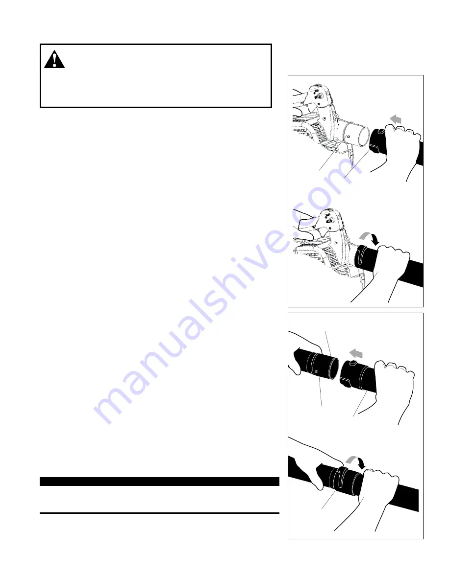
Assembling the Blower

Place the blower upright on the ground or on a sturdy work surface.
1.  Grasp the blower tube as shown, and push the tube over the blower dis-

charge port and locking pins.

2.  Lock the blower tube to the blower discharge port by rotating the tube as 

shown.

Blower

Tube

Locking Pin

Push the blower tube 

over the discharge port 

and locking pin

Rotate clockwise to lock

Nozzle

Locking Pin

Blower Tube

Push the nozzle 

over the blower 

tube and locking 

pin

Rotate clockwise to lock

1

3

2

4

3.  Grasp the nozzle with the mark “THIS SIDE UP” positioned as shown, 

and then push the nozzle over the straight tube and locking pins.

4.  Lock the nozzle to the straight tube by rotating the nozzle as shown.

Danger from

rotating impeller! 

Stop the engine before installing or removing the blower tubes! 

Never perform any maintenance or assembly procedures on this unit 

while the engine is running! 

WARNING!

IMPORTANT!

Blower tube installation affects both blower balance and performance! 

The tube and nozzle are correctly installed when the mark “THIS SIDE 

UP” is visible to the operator during normal operation.

Mark 

“THIS SIDE UP” 

must face up

Summary of Contents for EB254

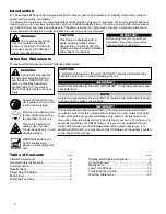
Page 1: ...ury to yourself and oth ers Read this manual and familiarize yourself with the contents Always wear eye and hearing protection when operating this unit WARNING SHINDAIWA OWNER S OPERATOR S MANUAL EB254 BLOWER X7501920500 03 10 ...

Page 2: ...ut compromise to quality comfort safety or durability The information contained in this manual describes units available at the time of production While every attempt has been made to give you the very latest information about your Shindaiwa EB254 blower there may be some differences between your EB254 blower and what is described here Shindaiwa reserves the right to make changes in production wit...

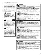
Page 3: ...udgement Minimize the Risk of Fire NEVER smoke or light fires near the unit ALWAYS stop the engine and allow it to cool before refueling Avoid over filling and wipe off any fuel that may have spilled ALWAYS inspect the unit for fuel leaks before each use During each refill check that no fuel leaks from around the fuel cap and or fuel tank If fuel leaks are evident stop using the unit immediately F...

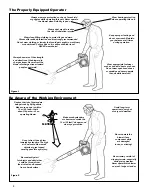
Page 4: ...rength and direction of the blower dis charge stream Never direct the blower discharge stream toward people or animals Avoid long term operation in very hot or very cold weather Make sure bystanders or observers outside the 15 m 50 feet danger zone wear eye protection Be extremely careful of slippery terrain especially during rainy weather Never operate this blower on a roof ledge or ladder Be con...

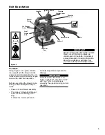
Page 5: ...witch Nozzle Blower Tube Contents Using Figure 3 as a guide familiar ize yourself with the blower and its components Understanding the unit helps ensure top performance longer service life and safer operation Before assembling the blower make sure you have all required compo nents Power unit and blower assembly This Owner s Operator s Manual and a tool kit containing a tool bag T Wrench 4 mm Hex W...

Page 6: ...alifornia models only Specifications Specifications are subject to change without notice Model EB254 Engine Type 4 cycle air cooled gasoline engine vertical cylinder Engine Bore x Stroke 34 mm x 27 mm 1 3 in x 1 1 in Engine Displacement 24 5cc 1 5 in3 Unit Weight without blower tube Less Fuel 4 9 kg 10 8 lb Unit Dimensions LxWxH 897 x 255 x 375 mm 35 x 10 x 15 in Fuel Tank Capacity 0 6 liter 20 0 ...

Page 7: ...pin Rotate clockwise to lock 1 3 2 4 3 Grasp the nozzle with the mark THIS SIDE UP positioned as shown and then push the nozzle over the straight tube and locking pins 4 Lock the nozzle to the straight tube by rotating the nozzle as shown Danger from rotating impeller Stop the engine before installing or removing the blower tubes Never perform any maintenance or assembly procedures on this unit wh...

Page 8: ...her engine components Fuel Requirements Gasoline Use 89 Octane R M 2 mid grade or higher gasoline known to be good quality Gasoline may contain up to 10 Ethanol grain alcohol or 15 MTBE methyl tertiary butyl ether Gasoline containing methanol wood alcohol is NOT approved Hybrid 4TM Mixture Oil Engine oil meeting ISO L EGD ISO CD 13738 and J A S O M345 FD standards must be used Shindaiwa highly rec...

Page 9: ... the fuel filler cap and tighten firmly 5 Wipe away any spilled fuel before starting the blower Filling the Fuel Tank Starting the Engine Starting Procedure 1 Place the blower on the ground 2 Prime the fuel system by repeat edly depressing the fuel primer bulb until no air bubbles are visible in the fuel discharge line The impeller will rotate whenever the blower is operated Never operate this blo...

Page 10: ...the engine still fails to start or fire refer to the troubleshooting flow chart at the end of this manual Pull upward rapidly Figure 7 The blower should now be ready for use Figure 6 Full Throttle Idle 4 Slide the ignition switch to the I ON position then depress the throttle lever half way and lock throttle by moving throttle lock lever halfway down See Figure 6 5 Hold the blower firmly with your...

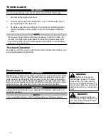
Page 11: ...ods of time On the opposite side a two position Limiter control allows full engine speed when set for Turbo or limits the throttle to a pre set engine speed when set to low noise dB setting Cruise Function Using the right thumb push the throttle lock lever down until the desired min 1 rpm setting is reached See Figure 10 To bring RPM down to idle push lever back up into original position Throttle ...

Page 12: ...ce replacement or repair of emission control devices and systems may be performed by any repair establishment or individual However war ranty repairs must be performed by a dealer or service center authorized by Echo Inc The use of parts that are not equivalent in performance and dura bility to authorized parts may impair the effectiveness of the emission control system and may have a bearing on t...

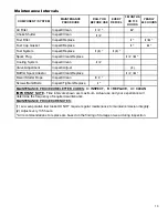
Page 13: ...tment Inspect Adjust 2 Muffler Spark Arrestor Inspect Clean Replace I C R Recoil Starter Rope Inspect Clean I C Screws Nuts Bolts Inspect Tighten Replace I MAINTENANCE PROCEDURE LETTER CODES I INSPECT R REPLACE C CLEAN IMPORTANT NOTE Time intervals shown are maximum Actual use and your experience will determine the frequency of required maintenance MAINTENANCE PROCEDURE NOTES 1 Low evaporative fue...

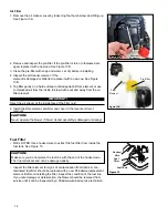
Page 14: ... the inside face of the filter only 6 Install the filter element pre filter and cover in the reverse order of removal CAUTION Never operate the blower if the air cleaner assembly is damaged or missing Air Filter Fuel Filter 63008 FUEL FILTER Use a hooked wire to extract the fuel filter from inside the fuel tank See Figure 15 CAUTION Make sure you do not pierce the fuel line with the end of the hoo...

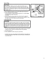
Page 15: ...irmly with the spark plug wrench If a torque wrench is available torque the spark plug to 16 7 18 6 Nm 148 165 inch pounds Spark Plug Cooling System CAUTION The engine is cooled by air drawn into the air intake cover on the blower housing The blower fan then pushes the cooling air through an opening in the fan housing forcing it past the cylinder cooling fins Failure to keep the cooling system and...

Page 16: ...ack off just enough to allow gauge to slip out with limited resistance 5 While holding adjustment screw in place with Allen driver tighten lock nut with wrench 6 Turn engine over several times and return to TDC compression Re check with proper feeler gauge to make sure clearance adjustment did not change as a result of tightening locknut Readjust as necessary 7 Replace rocker arm cover gasket to a...

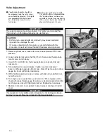
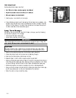
Page 17: ... after servicing have the unit inspected by an authorized servicing Shindaiwa dealer Muffler Arrester Screen Figure 16 Arrester Screen Cover Exhaust System Carburetor Adjustment Engine Break In New engines must be operated a minimum duration of two tanks of fuel break in before carburetor adjustments can be made During the break in period your engine performance will increase and exhaust emissions...

Page 18: ... use in thirty 30 days ninety 90 days when a fuel stabilizer is added CAUTION Gasoline stored in the carburetor for extended periods can cause hard starting and could also lead to increased service and maintenance cost Remove the remaining fuel from the fuel lines and carburetor 1 Prime the primer bulb until no more fuel is passing through 2 Start and run the engine until it stops running 3 Repeat...

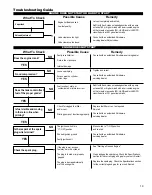
Page 19: ...ilter and or vent Priming pump not functioning properly The ignition switch is in O OFF position Shorted ignition ground Faulty ignition unit If the plug is wet excess fuel may be in the cylinder The plug is fouled or improperly gapped The plug is damaged internally or of the wrong size Consult with an authorized Shindaiwa servicing dealer Tighten and re test Consult with an authorized Shindaiwa s...

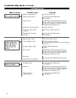
Page 20: ... classified oils at 50 1 gasoline oil ratio Clean the intake cover Clean repair or replace as necessary Consult with an authorized Shindaiwa servicing dealer Service the air cleaner element Tighten or replace the spark plug Check the Specifications section for the correct plug and gap for your unit Repair or replace fuel filter and or fuel line Refill with fresh clean unleaded gasoline with a pump ...

Page 21: ...ubleshooting Guide continued Valve cover is leaking Consult with an authorized Shindaiwa servicing dealer Top of engine is getting dirty and oily Idle set too high Adjust idle Check Specifications page for correct idle speed Engine will not idle down Engine has an air leak Consult with an authorized Shindaiwa servicing dealer Debris build up in impeller Loose or damaged impeller Loose or damaged e...

Page 22: ... questions concerning Shindaiwa s Warranty Statement you can contact our Consumer Product Support Department at 1 800 673 1558 or contact us through the web at WWW SHINDAIWA COM PRODUCT WARRANTY PERIOD RESIDENTIAL APPLICATION 2 YEAR WARRANTY Units for residential or non income producing use will be covered by this limited warranty for two 2 years from date of purchase EXCEPTIONS For engine powered...

Page 23: ... manual is the customer s responsibility Failures due to improper set up pre delivery service or repair service by anyone other than authorized Shindaiwa servicing dealer during the warranty period Certain parts and other items are not warranted including but not limited to lubricants starter cords and engine tune ups Use of spark plugs other than those meeting performance and durability requireme...

Page 24: ...gned built and equipped to conform with applicable EPA and C A R B emissions standards and that your equipment SORE is free from defects in material and workmanship that would cause it to fail to conform with applicable requirements for 2 years or the length of the ECHO Inc warranty whichever is longer The warranty period begins on the date the product is purchased by an end user HOW WILL A COVERE...

Page 25: ...25 NOTES ...

Page 26: ...26 NOTES ...

Page 27: ...27 NOTES ...

Page 28: ...7 986 7783 Dealer information is also available on WWW SHINDAIWA COM When presenting your unit for Warranty service repairs proof of purchase is required Consumer Product Support If you require assistance or have questions concerning the application operation or maintenance of this product you may call the Shindaiwa Consumer Product Support Department at 1 877 986 7783 from 8 30 am to 4 30 pm Cent...

Reviews: