background image

TROUBLESHOOTING

T262

36

X7502342100

© 4/2017 ECHO Inc.

TROUBLESHOOTING

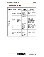
ENGINE PROBLEM TROUBLESHOOTING CHART

Problem Check  Status 

Cause 

Remedy 

Engine 
cranks - 
starts 
hard - 
doesn’t 
start

Fuel at 
carburetor

No fuel at 
carburetor

Fuel strainer 
clogged - 
Fuel line 
clogged - 
Carburetor

Clean or replace - 
Clean or replace - 
See your Shindaiwa 
dealer

Fuel at 
cylinder

No fuel at 
cylinder

Carburetor

See your Shindaiwa 
dealer

Muffler 
wet with 
fuel

Fuel Mixture 
too rich

OPEN choke - 
Clean/replace air 
filter - Adjust carbu-
retor - See your 
Shindaiwa dealer

Spark at 
end of 
plug wire

No spark

Stop switch 
OFF -         
Electrical  
problem - 
Interlock 
switch

Turn switch to ON - 
See your Shindaiwa 
dealer - See your 
Shindaiwa dealer

Spark at 
plug

No spark

Spark gap 
incorrect - 
Covered with 
carbon - 
Fouled with 
fuel - Plug 
defective

Adjust to 0.65mm 
(0.026 in.) - Clean 
or replace - Clean or 
replace - Replace 
plug

Summary of Contents for PS262

Page 1: ... and surrounding cover may become extremely hot Always keep clear of exhaust and muffler area otherwise serious personal injury may occur The engine exhaust from this product contains chemicals known to the State of California to cause cancer birth defects or other reproductive harm Users of this equipment risk injury to themselves and others if the unit is used improperly and or safety precaution...

Page 2: ...fety Equipment 7 Equipment 11 Emission Control Exhaust Evaporative 12 CARB And EPA Emissions Control Information 12 Description 13 Contents 15 Assembly 16 Support Handle 16 Operation 16 Fuel 17 Starting Cold Engine 19 Starting Warm Engine 20 Stopping Engine 22 Sweeping Operation 22 Maintenance 24 Skill Levels 24 Maintenance Intervals 24 Air Filter 25 Fuel Filter 26 Spark Plug 27 Cooling System 28 ...

Page 3: ...T262 TABLE OF CONTENTS X7502342100 3 4 2017 ECHO Inc ENGLISH ...

Page 4: ...DAIWA Parts and Assemblies for your SHINDAIWA products are available only from an Authorized SHINDAIWA Dealer When you do need to buy parts always have the Model Number and Serial Number of the unit with you You can find these numbers on the engine housing For future reference write them in the space provided below Model No _________________ SN ___________________ Service Service of this product d...

Page 5: ...d ECHO if we find it necessary to contact you Additional or Replacement Manuals Replacement Operator and Parts Catalogs are available from your SHINDAIWA dealer or at WWW SHINDAIWA USA COM or by contacting the Consumer Product Support Department 1 877 986 7783 Always check WWW SHINDAIWA USA COM for updated information SAFETY Manual Safety Symbols and Important Information Throughout this manual an...

Page 6: ...ips for use care and main tenance of the unit CIRCLE AND SLASH SYMBOL This symbol means the specific action shown is prohibited Ignoring these prohibitions can result in serious or fatal injury International Symbols Symbol Description Symbol Description Warning See Operator s Manual Carburetor Adjustment High Speed Mixture Wear Eye Ear and Head Protection Carburetor Adjustment Idle Speed Wear Hand...

Page 7: ...parks Near Fuel Ignition ON OFF DO NOT Smoke Near Fuel Primer Bulb Choke Control RUN Position Choke Open Choke Control COLD START Position Choke Closed Keep Bystanders and Helpers Away 15 m 50 ft Thrown Objects Rotating Cutting Attachment Symbol Description Symbol Description ...

Page 8: ... safety a full face shield may be worn over safety glasses or goggles to provide protection from sharp branches or flying debris Hand Protection Wear sturdy no slip rubber work gloves to improve your grip on the han dles Gloves also provide protection against cuts and scratches cold envi ronments and reduce the transmission of machine vibration to your hands Hearing Ear Protection ECHO recommends ...

Page 9: ... operator fatigue which may lead to heat stroke Schedule heavy work for early morning or late afternoon hours when temperatures are cooler The components of this machine generate an electromagnetic field during operation which may interfere with some pacemak ers To reduce the risk of serious or fatal injury persons with pacemakers should consult with their physician and the pace maker manufacturer...

Page 10: ...experience discomfort red ness and swelling of the fingers followed by whitening and loss of feeling consult your physician before further exposing yourself to cold and vibra tion Repetitive Stress Injuries RSI It is believed that overusing the muscles and tendons of the fingers hands arms and shoulders may cause soreness swelling numb ness weakness and extreme pain in those areas Certain repetiti...

Page 11: ...rical current Never touch wires directly or indirectly otherwise serious injury or death may result Do not operate this product indoors or in inadequately ventilated areas Engine exhaust contains poisonous emissions and can cause serious injury or death Read the Manuals Provide all users of this equipment with the Operator s Manual for instructions on Safe Operation Clear the Work Area Spectators ...

Page 12: ...ws Tighten and or replace as needed Inspect unit for damage and broken missing or incorrectly installed parts Check that the attachment is correctly installed and in safe operating condition Assure all safety devices are attached and that unit is as clean as possible Moving parts can amputate fingers or cause severe injuries Keep hands clothing and loose objects away from all openings ALWAYS stop ...

Page 13: ...ngine Family on the Emis sion Control Information label sam ple below is B C K or T the emission control system is EM and TWC 3 way catalyst The fuel tank fuel line emission control system is EVAP evaporative emissions Evaporative emissions for California models are only applicable to fuel tanks An Emission Control Label is located on the engine This is an EXAMPLE ONLY information on label varies ...

Page 14: ...SCRIPTION Locate the safety decal s on your unit Make sure the decal s is legible and that you understand and follow the instructions on it If a decal cannot be read a new one can be ordered from your dealer 10 11 12 13 14 15 16 17 18 1 2 3 4 5 6 7 8 9 ...

Page 15: ...gger Lockout 4 Stop Switch 5 Throttle Trigger 6 Support Handle For Left Hand 7 Drive Shaft Assembly 8 Gear Case 9 Gear Output Shaft 10 Spark Plug 11 Top Guard 12 Spark Arrestor Muffler Or Spark Arrestor Muffler With Catalyst 13 Fuel Tank 14 Fuel Tank Cap 15 Recoil Starter Handle 16 Purge Bulb 17 Choke 18 Air Cleaner ...

Page 16: ...convenience Due to packaging restrictions some assembly may be necessary After opening the carton check for damage Immediately notify your retailer or SHINDAIWA Dealer of damaged or missing parts Use the contents list to check for missing parts 1 Power Head Drive Shaft Assembly 1 Operator s Manual 1 Warranty Sheet 1 Safety Goggles ...

Page 17: ...removing obstructions clearing debris or servicing unit Engine exhaust IS HOT and contains Carbon Monoxide CO a poison gas Breathing CO can cause unconsciousness serious injury or death Exhaust can cause serious burns ALWAYS po sition unit so that exhaust is directed away from your face and body Operation of this equipment may create sparks that can start fires around dry vegetation This unit is e...

Page 18: ... containing methanol wood alcohol is NOT approved ECHO Red Armor Fuel Power Fuel is 93 octane ethanol free fuel premixed with ECHO Red Armor engine oil at 50 1 ratio Use of ECHO Red Armor Fuel Power Fuel is recommended to extend engine life in all air cooled 2 stroke and 2 4 stroke hybrid engines Two Stroke Oil A two stroke engine oil meeting ISO L EGD ISO CD 13738 and J A S O FD Standards must be...

Page 19: ...tions 1 Fill an approved fuel container with half of the required amount of gasoline 2 Add the proper amount of engine oil to gasoline 3 Close container and shake to mix oil with gasoline 4 Add remaining gasoline close fuel container and remix Spilled fuel is a leading cause of hydrocarbon emissions Some states may require the use of automatic fuel shut off containers to reduce fuel spillage After...

Page 20: ... before each use Used oil and gasoline and soiled towels are hazardous waste materials Disposal laws vary by locality Starting Cold Engine The attachment will operate immediately when the engine starts and could result in possible serious injury Keep movable parts of the attachment away from objects that could become entangled or thrown and surfaces that could cause loss of control 1 Stop Switch M...

Page 21: ... engine fires or 5 pulls move choke B to the RUN OPEN position Firmly grasp throttle handle and throttle trigger lockout with left hand and fully depress throttle trigger to wide open position Pull starter handle rope until engine starts and runs Release throttle trigger and allow unit to warm up at idle for several minutes Note If engine does not start with choke in Run position after 5 pulls rep...

Page 22: ...itch A away from the STOP position 2 Purge Bulb Pumppurgebulb C untilfuel is visible and flows freely in the clear fuel tank return line Pump bulb an additional 4 or 5 times 3 Recoil Starter Lay the unit on a flat area and keep movable attachment parts clear of all obstacles Firmly grip throttle handle and throttle trigger lockout with left hand Rapidly pull recoil starter handle rope D until engi...

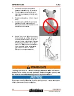
Page 23: ...ART position to stall engine Have your dealer repair stop switch before using unit again Sweeping Operation Always beware of thrown debris Do not operate with paddles close to your body which could result in loss of control and possible serious injury If drum assemblies jam switch engine off and inspect attachment for damage Never operate around objects that could entangle the drums or cause loss ...

Page 24: ...is may be swept out and away from corners by turning unit over to reverse paddle direction Grip unit securely using both hands Operate throttle trigger with thumb of right hand For extended use reposition front handle to allow comfortable grip Return handle to normal position for regular operation Turning unit over to reverse sweeper drum rotation will cause debris to be swept toward operator Redu...

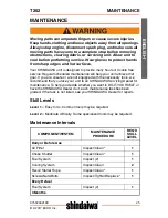
Page 25: ...l If you are unsure or are not equipped with the necessary tools we recommend that you take your unit to an SHINDAIWA Servicing Dealer for maintenance To help you decide whether you want to DO IT YOURSELF or have the SHINDAIWA Dealer do it each maintenance task has been graded If the task is not listed see your SHINDAIWA Dealer for repairs Skill Levels Level 1 Easy to do Common tools may be requir...

Page 26: ...e COLD START position This prevents dirt from entering the carburetor throat when the air filter is removed Brush accumulated dirt from air cleaner area 2 Remove air filter cover Brush dirt from inside cover Assure throttle wire retaining clip remains in place as shown when removing or installing air filter cover Air Filter Replace 1 Fuel Filter Inspect 1 Fuel Cap Gasket Inspect 1 Spark Plug Inspe...

Page 27: ...do not wring dry Allow to dry completely before reuse Do not oil Air Filter Lightly brush debris from filter Replace filter if it is damaged fuel soaked very dirty or the rubber sealing edges are deformed 5 Assemble components in reverse order Assure air filter is assembled with pleats oriented vertically Fuel Filter Level 1 Fuel is VERY flammable Use extreme care when mixing storing or handling o...

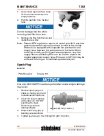
Page 28: ...se between the carburetor and fuel tank When servicing model year 2012 and later equipment only fuel supply hoses certified by EPA can be used to replace the original equipment supply hose Fines up to 37 500 may be enforced for using an un certified replacement part Spark Plug Level 2 Use only NGK CMR7H spark plug otherwise severe engine damage may occur 1 Remove spark plug and check for fouling w...

Page 29: ...e operating temperatures cooling air must pass freely through the cylinder fin area This flow of air carries combustion heat away from the engine Overheating and engine seizure can occur when Air intakes are blocked preventing cooling air from reaching the cylinder Parts Required None if you are careful ...

Page 30: ...ered Normal Maintenance Any failure attributed to lack of maintenance is not warranted 1 Remove spark plug lead 2 Remove muffler cover A 3 Remove engine cover B DO NOT use a metal scraper to remove dirt from the cylinder fins 4 Use brush to remove dirt from the cylinder fins 5 Remove grass and leaves from the grid between the recoil starter and fuel tank 6 Assemble components in reverse order Exha...

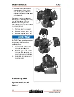
Page 31: ...its from muffler components Note When cleaning carbon deposit be careful not to damage the catalytic element inside muffler 6 Replace screen if it is cracked plugged or has holes burned through 7 Assemble components in reverse order Exhaust Port Cleaning Level 2 1 Remove spark plug lead from spark plug and remove muffler cover 2 Place piston at top dead center Remove muffler A and heat shield B Pa...

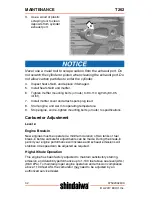
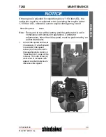
Page 32: ...arm to operating temperature 9 Stop engine and re tighten mounting bolts or nuts to specifications Carburetor Adjustment Level 2 Engine Break In New engines must be operated a minimum duration of two tanks of fuel break in before carburetor adjustments can be made During the break in period your engine performance will increase and exhaust emissions will stabilize Idle speed can be adjusted as req...

Page 33: ...is run at the factory and the carburetor is set in compliance with emission regulations Carburetor adjustments other than idle speed must be performed by an authorized dealer 1 Check idle speed and reset if necessary If a tachometer is available idle speed screw A should be set to the specifications found on Specifications page of this manual Turn idle screw A clockwise to increase idle speed coun...

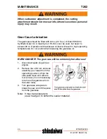
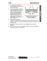
Page 34: ...n with excessive oil level will result in high operating temperatures Do not overfill when replacing the gearcase oil BURN DANGER The gearcase will be extremely hot after use 1 Disconnect spark plug wire at engine 2 Remove the LH Drum and axle assembly as viewed from the operating position Wipe the side plate clean and remove four screws it is not necessary to remove the gearcase from the outer tu...

Page 35: ...4 Synthetic Gear Oil to the bottom of the chamfer on the output gear The correct oil depth is 5 8 in 15 5 mm DO NOT OVERFILL 6 Inspect the side plate for damage and clean off all remaining liquid gasket material with brake cleaner or acetone Coat the outer sealing flange of the side plate with silicon sealant 7 Replace the cover and install the four side plate screws Tighten securely 8 Reinstall t...

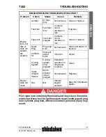
Page 36: ...aler Fuel at cylinder No fuel at cylinder Carburetor See your Shindaiwa dealer Muffler wet with fuel Fuel Mixture too rich OPEN choke Clean replace air filter Adjust carbu retor See your Shindaiwa dealer Spark at end of plug wire No spark Stop switch OFF Electrical problem Interlock switch Turn switch to ON See your Shindaiwa dealer See your Shindaiwa dealer Spark at plug No spark Spark gap incorr...

Page 37: ...filter Fuel filter dirty Contami nants residues in fuel Replace Fuel vent Fuel vent plugged Contami nants residues in fuel Clean or replace Spark Plug Plug dirty worn Normal wear Clean and adjust or replace Carbure tor Improper adjust ment Vibration Adjust Cooling System Cooling system dirty plugged Extended operation in dirty dusty locations Clean Spark Arrestor Screen Spark arrestor screen plugg...

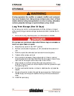
Page 38: ... 2 Place the stop switch in the OFF position 3 Remove accumulation of grease oil dirt and debris from exterior of unit 4 Perform all periodic lubrication and services that are required 5 Tighten all the screws and nuts 6 Drain fuel tank completely Press purge bulb 6 7 times to remove remaining fuel from carburetor then drain the tank again Close choke start and run the engine until it stops due to...

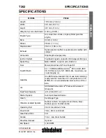
Page 39: ... in Fuel Mixed Gasoline and Two stroke Oil Fuel Oil Ratio 50 1 SHINDAIWA Red Armor ISO L EGD ISO CD 13738 and J A S O M345 FD two stroke air cooled engine oil Gasoline Use 89 Octane unleaded Do not use fuel containing methyl alcohol more than 10 ethyl alcohol or 15 MTBE Do not use alternative fuels such as E15 or E85 Oil SHINDAIWA Red Armor Premium Universal 2 Stroke Oil Fuel Tank Capacity 61L 20 ...

Page 40: ... will never be sold or misused by ECHO Inc Registering your purchase enables us to contact you in the unlikely event of a service update or product recall and verifies your ownership for warranty consideration If you do not have access to the Internet you can complete the form below and mail to ECHO Inc Product Registration PO Box 1139 Lake Zurich IL 60047 Clutch Engagement Speed 4 300 RPM Wide Op...

Page 41: ...T262 PRODUCT REGISTRATION X7502342100 41 4 2017 ECHO Inc ENGLISH ...

Page 42: ...NOTES T262 42 X7502342100 4 2017 ECHO Inc NOTES ...

Page 43: ...T262 NOTES X7502342100 43 4 2017 ECHO Inc ENGLISH ...

Page 44: ...ECHO INCORPORATED 400 Oakwood Road Lake Zurich IL 60047 www echo usa com T99715001001 T99715999999 ...

Reviews: