57(63)
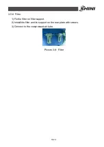
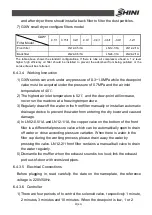
and after dryer there should install a back filter to filter the dust particles.
7)
GXW small dryer configure filters model
GXW*
Filter Model
-0.1/1
0.15/1
0.2/1
-0.3/1
-0.4/1
-0.6/1
-0.9/1
-1.2/1
Front filter
LN12-0.5/1A
LN12-1/1A
LN12-2/1A
Back filter
LN24-0.5/1A
LN24-1/1A
LN24-2/1A
The table above shows the standard configurations. If there is lube air compressor ahead, a 1~2 level
higher high efficiency oil filter should be installed to prevent the adsorbent from being polluted, or the
service life will be shortened.
6.4.3.4 Working Instruction
1) GXW series can work under any pressure of 0.3~1.0MPa while the dew-point
value must be acquired under the pressure of 0.7MPa and the air inlet
temperature of 40
℃
.
2) The highest air inlet temperature is 52
℃
and the dew-point will increase,
never run the machine at a freezing temperature.
3) Regularly draw off the water in the front filter manually or install an automatic
drainage device to prevent the water from entering the dry tower and caused
damage.
4) In LN12-0.5/1A and LN12-1/1A, the copper valve on the bottom of the front
filter is a differential pressure valve which can be automatically open to drain
off water or close according pressure variation. When there is water in the
filter cup during the working process, please drain away the water by
pressing the valve. LN12-2/1 front filter contains a manual ball valve to drain
the water regularly.
5) Dismantle the muffler when the exhaust sound is too loud; link the exhaust
port out-of-door with oversized pipes.
6.4.3.5 Electrical Connections
Before plugging in, read carefully the date on the nameplate, the reference
voltage is 220V/50Hz.
6.4.3.6 Controller
1) There are four periods of to control the solenoid valve, respectively 1 minute,
2 minutes, 3 minutes and 10 minutes. When the dew-point is low, 1 or 2
Summary of Contents for SDL-U Series
Page 1: ...SDL U HD Series Heatless Dehumidifying Compact Dryer Date Nov 2014 Version Ver B English...
Page 2: ......
Page 11: ...11 63 1 3 2 Outline Drawing Picture 1 1 Outline Drawing...
Page 17: ...17 63 Picture 2 1 Working Principle...
Page 27: ...27 63 2 3 2 Main Circuit SDL 20U 450U HD Picture 2 6 Main Circuit SDL 20U 450U HD...
Page 28: ...28 63 2 3 3 Control Circuit SDL 20U 450U HD Picture 2 7 Control Circuit 1 SDL 20U 450U HD...
Page 29: ...29 63 Picture 2 8 Control Circuit 2 SDL 20U 450U HD...
Page 38: ...38 63 Picture 2 10 Main electrical circuit SDL 600U 1200U HD...
Page 39: ...39 63 2 3 7 Control circuit SDL 600U 1200U HD Picture 2 11 Control circuit 1 SDL 600U 1200U HD...
Page 40: ...40 63 Picture 2 12 Control circuit 1 SDL 600U 1200U HD...

