44(62)
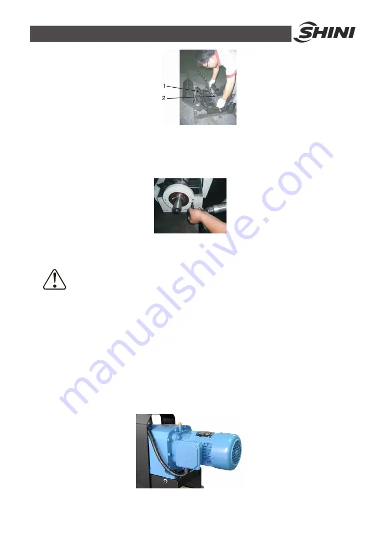
Picture 3-4
:
Installation of Bearing and Blade Rest 2
4) Fix the bearing base on the cutting chamber.
Picture 3-5
:
Installation of Bearing and Blade Rest 1 3
Notice!
Daub the lubrication on the bearing and bearing base. Use proper
twisting force to lock the screw tightly.
3.4 Installation of Gear Motor and Coupling
1) After complete the mounting of blade rest and cutting chamber to the base.
Align blade shaft to the grooves on coupling to mount the key and also mount
coupling on the blade shaft,
2) Put the gear motor on its fixing plate and its connecting key lies in the main
shaft groove. Insert main shaft after align itself with coupling. Screw up with
four screws (M12x40).
Picture 3-6
:
Installation of Gear Motor and Coupling
Summary of Contents for SG-14 Series
Page 1: ...SG 14 Series Screenless Granulators Date Dec 2014 Version Ver B English ...
Page 2: ......
Page 8: ...8 62 ...
Page 13: ...13 62 1 3 2 Dimensions Picture 1 1 Dimensions ...
Page 30: ...30 62 2 3 Electrical Diagram 2 3 1 Main Circuit 400V Picture 2 12 Main Circuit 400V ...
Page 31: ...31 62 2 3 2 Control Circuit 400V Picture 2 13 Control Circuit 1 400V ...
Page 32: ...32 62 Picture 2 14 Control Circuit 2 400V ...
Page 33: ...33 62 2 3 3 Components Layout 400V Picture 2 15 Components Layout 400V ...
Page 35: ...35 62 2 3 5 Main Electrical Circuit 230V Picture 2 16 Main Electrical Circuit 230V ...
Page 36: ...36 62 2 3 6 Control Circuit 230V Picture 2 17 Control Circuit 1 230V ...
Page 37: ...37 62 Picture 2 18 Control Circuit 2 230V ...
Page 38: ...38 62 2 3 7 Components Layout 230V Picture 2 19 Components Layout 230V ...


