33(65)
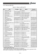
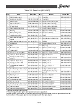
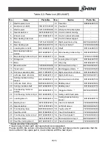
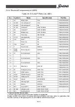
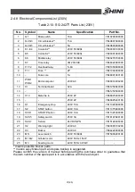
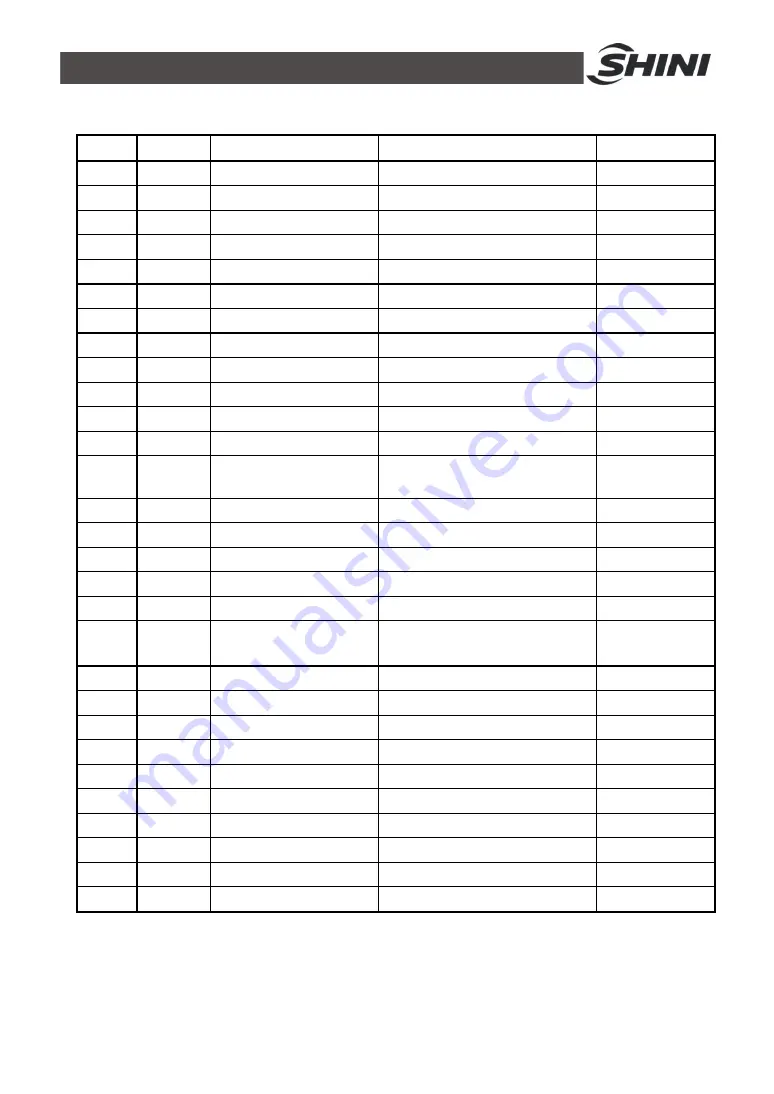
Table 2-9: SG-2436T/2446T Parts List (400V)
No.
Symbol
Name
Specification
Part No.
1
Q1
Mian switch
16A
YE10200300000
2
Q2 Q3
Circuit breaker**
15A
YE40601500000
3
Q2 Q3
Circuit breaker**
5A
YE40603000000
4
K1~K4
Contactor**
230V 50/60Hz
YE00300100000
5
K5
Contactor**
230V 50/60Hz
YE00301000000
6
K6
Middle relay
230V 50/60Hz
YE03270700000
7
K7
Time relay
3M 230VAC
YE86322000000
8
F1 F2
Overload relay
4~6.3A
YE01046300100
9
FU1
Fuse**
2P
YE41032200000
10
-
Fuse core
1A
YE46001000100
11
FU2
Fuse**
2A
YE41001000000
12
T
Transformer
500mA
YE70402300800
13
PCB1
PCB2
Microcomputer
230VAC
YE80012200200
14
X1
Terminal board
32A
YE61250040000
15
-
-
-
YE61253500000
16
-
Terminal board
32A
YE61250040000
17
-
-
-
YE61253500000
18
-
Terminal board
32A
YE61250040000
19
X10
Metal tie in
250V 4P
YE68025400000
YE68025400100
20
S1
Emergency stop
400V 10A
YE11320300000
21
S2
STOP button
400V 10A
YE11375800000
22
S3 H1
STARTP button
400V 10A
YE11325300000
23
S4 S5
Safety switch
250V 3A
YE16147600100
24
S6 S7
Sensor
24VDC NPN
YE15122400000
25
H2
Warning light
230VAC
YE83305100200
26
H3
Buzzer
230VAC
YE84222000000
27
MS
Level switch
230V 50/60Hz
YE15000200100
28
M1 M2
Grinder motor
400V 50Hz 2.2kW
-
29
M3
Feeding motor
400V 50Hz 0.37kW
-
* means possible broken parts.
** means easy broken part. and spare backup is suggested.
Please confirm the version of manual before placing the purchase order to guarantee that
the item number of the spare part is in accordance with the real object.
Summary of Contents for SG-24T
Page 1: ...SG 24T Screenless Granulator Date Apr 2013 Version Ver B English...
Page 2: ......
Page 8: ...8 65...
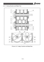
Page 25: ...25 65 2 3 3 Cutting Chamber and Blade Rest Picture 2 5 Cutting Chamber and Blade Rest...
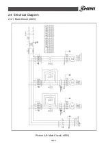
Page 29: ...29 65 2 4 Electrical Diagram 2 4 1 Main Circuit 400V Picture 2 9 Main Circuit 400V...
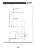
Page 30: ...30 65 2 4 2 Control Circuit 400V Picture 2 10 Control Circuit 400V...
Page 31: ...31 65 2 4 3 Electrical Components Layout 400V Picture 2 11 Electrical Components Layout 400V...
Page 34: ...34 65 2 4 5 Main Circuit 230V Picture 2 12 Main Circuit 230V...
Page 35: ...35 65 2 4 6 Control Circuit 230V Picture 2 13 Control Circuit 230V...
Page 36: ...36 65 2 4 7 Electrical Components Layout 230V Picture 2 14 Electrical Components Layout 230V...
Page 40: ...40 65 2 5 4 Proportional Valves Picture 2 18 Control Cabinet and Valve...


