54(65)
Caution!
If there are ungrinded materials in the feed box or cutting chamber, the
granulator shall NOT be stopped, otherwise raw materials will block the
rotor and the motor will be overloaded next time you start the machine
up.
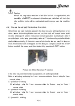
4.6 Motor Reversed Protective Function
When there are hard material appear in the feed box and cutting chamber or for
other reason the cutting blades can not cut, this unit will enable blade shaft
reverse rotating with alarm, it resumes normal operation automatically after 3
seconds later, so to keep granulating material. The alarm dies out after blade
shaft rotates normally. If the motor reverse function be started over 3-4 times or
more, the motor would be stopped. At this time you can press down the STOP
button to cut off the power, and then restart it by press the START button.
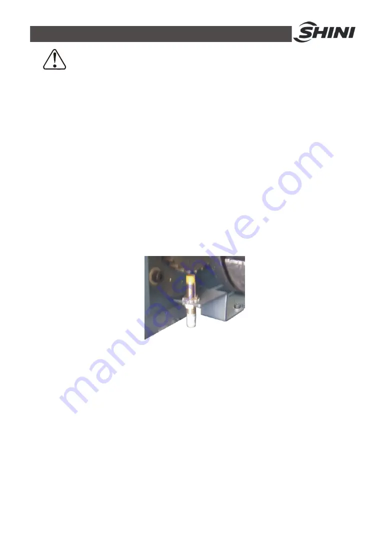
Picture 4-4: Motor Reversed Protection
If the rotor has been seized during operation, its working mode is:
Rotor is seized up, auto stop for 1 sec
→
reverse rotate for 3 secs
→
stop for 1 sec
→
normal rotate
→
A. 1) normal
→
working
2) seized up
→
stop for 1 sec
→
reverse rotate for 3 secs
→
stop for 1 sec
→
normal rotate
B. 1) normal
→
working
2) seized up
→
stop for 1 sec
→
reverse rotate for 3 secs
→
stop for 1 sec
→
normal rotate
C. 1) normal
→
working
Summary of Contents for SG-24T
Page 1: ...SG 24T Screenless Granulator Date Apr 2013 Version Ver B English...
Page 2: ......
Page 8: ...8 65...
Page 25: ...25 65 2 3 3 Cutting Chamber and Blade Rest Picture 2 5 Cutting Chamber and Blade Rest...
Page 29: ...29 65 2 4 Electrical Diagram 2 4 1 Main Circuit 400V Picture 2 9 Main Circuit 400V...
Page 30: ...30 65 2 4 2 Control Circuit 400V Picture 2 10 Control Circuit 400V...
Page 31: ...31 65 2 4 3 Electrical Components Layout 400V Picture 2 11 Electrical Components Layout 400V...
Page 34: ...34 65 2 4 5 Main Circuit 230V Picture 2 12 Main Circuit 230V...
Page 35: ...35 65 2 4 6 Control Circuit 230V Picture 2 13 Control Circuit 230V...
Page 36: ...36 65 2 4 7 Electrical Components Layout 230V Picture 2 14 Electrical Components Layout 230V...
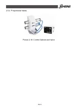
Page 40: ...40 65 2 5 4 Proportional Valves Picture 2 18 Control Cabinet and Valve...

