19(77)
2. Structural Features and Working Principle
2.1 General Description
SGS-S series are suitable for crushing plastics including wastes of injection
molding, blow molding or extrusion molding; it is a must to clear away metal
dust and dirt before crushing.
2.1.1 Working Principle
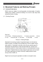
Parts name:
A. Feed hopper
B. Material pushing block
C. Hydraulic pump station
D. Motor
E. V belt
F. Reduction gear G. Cutter shaft
H. Fixed blade
I. Screen
Picture 2-1: Working Principle
Wastes fall into crushing chamber through feed hopper (A). Activated by
hydraulic system, oil cylinder drives pushing block to move wastes close to
cutter shaft (G). Cutter shaft is driven by motor (D) plus reduction gear (F).
Wastes then are granulated by rotate and fixed blade (H), granule size is
controlled by screen (I), which locates in bottom of crushing chamber for easy
replacement. Regrinds falls into storage hopper though screen and conveyed
by V-belts to granulators for further crushing. Feeding methods include
conveyor belt or forklift, etc.
Regrind can be conveyed to granulators via belts or conveyed to store.
Summary of Contents for SGS-6080S
Page 1: ...SGS S Single shaft Shredders Date May 2014 Version Ver B English...
Page 2: ......
Page 8: ...8 77...
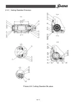
Page 24: ...24 77 2 3 3 Cutting Chamber Structure Picture 2 8 Cutting Chamber Structure...
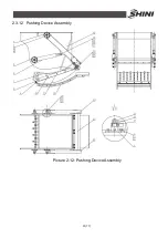
Page 31: ...31 77 2 3 12 Pushing Device Assembly Picture 2 12 Pushing Device Assembly...
Page 37: ...37 77 2 4 Wiring Diagram 2 4 1 Wiring Diagram Picture 2 16 Wiring Diagram...
Page 38: ...38 77 2 4 2 Control Wiring Diagram Picture 2 17 Control Wiring Diagram 1...
Page 39: ...39 77 Picture 2 18 Control Wiring Diagram 2...
Page 40: ...40 77 2 4 3 Electrical Components Layout Picture 2 19 Electrical Components Layout 1...
Page 41: ...41 77 Picture 2 20 Electrical Components Layout 2...

