25(77)
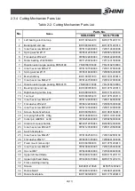
2.3.4 Cutting Mechanism Parts List
Table 2-2: Cutting Mechanism Parts List
Parts No.
No.
Name
SGS-6080S
SGS-75120S
1
Left bearing erection loop
BH11801242010
BW31751201710
2
Bearing left end cap
BH10801020010
BH10751201310
3
Inner hex screw M10x40*
YW61104000000
YW61104000000
4
Spring washer
Ø
10*
YW65012000000
YW65012000000
5
Flat washer
Ø
12x24*
YW66122400000
YW66122400000
6
Roller bearing 23028CDE4
YW11230280000
YW11231300000
7
Rotation axis lip-type packing FB160190
YR20160190000
YR20182100000
8
Inner hex screw M16x70*
YW61167000000
YW61167000000
9
Spring washer
Ø
16*
YW65016000000
YW65016000000
10
Main shaft key
BH11801070010
BH11801070010
11
Inner hex screw M24x70*
YW61247000000
YW61247000000
12
Rotation axis lip-type packing FB140170
YR20140170000
YR20160190000
13
Bearing right end cap
BH10801050010
BH10751200310
14
Right bearing rection loop
BH10801320010
BW31751201810
15
Tool rest
BH10801200210
BH10751200110
16
Inner hex screw M12x45*
YW61124500000
YW61166000000
17
Flat washer
Ø
12x24*
YW66122400000
YW65016000000
18
Inner hex screw M14x30*
YW61143000000
YW61143000000
19
Screen frame fixed block
BH10801560010
BH10801560010
20
Air spring 525x200 90kg
YW01060000100
YW01170010000
21
Cotter pin GB9586 4x30
YW09254000000
YW09254000000
22
Aluminum square handle
BW20012000040
BW20012000040
23
Inner hex screw M12x45*
YW61123500000
YW61123500000
24
Switch fixed plate
-
-
25
Inner hex screw M6x25*
YW61062500100
YW61062500100
26
Flat washer
Ø
6x13*
YW66061300000
YW66061300000
27
Fixed mount manuscript
BH10801060010
BH10751200410
28
Inner hex screw M8x40*
YW61084000000
YW61085000000
29
Hex nut M8*
YW64080600000
YW64080600000
30
Upper left fixed blade
YW43801200000
BW31751201110
31
Upper right fixed blade
YW43801070000
BW31751201210
32
Frame welding drawing
-
-
33
Screen
BL53801210020
BL53751200320
34
Rotate blade*
YW43801290000
YW43801290000
35
Rotate fixed plate
BH11801290010
BH11751200410
Summary of Contents for SGS-6080S
Page 1: ...SGS S Single shaft Shredders Date May 2014 Version Ver B English...
Page 2: ......
Page 8: ...8 77...
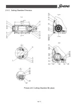
Page 24: ...24 77 2 3 3 Cutting Chamber Structure Picture 2 8 Cutting Chamber Structure...
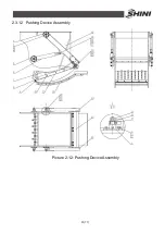
Page 31: ...31 77 2 3 12 Pushing Device Assembly Picture 2 12 Pushing Device Assembly...
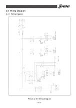
Page 37: ...37 77 2 4 Wiring Diagram 2 4 1 Wiring Diagram Picture 2 16 Wiring Diagram...
Page 38: ...38 77 2 4 2 Control Wiring Diagram Picture 2 17 Control Wiring Diagram 1...
Page 39: ...39 77 Picture 2 18 Control Wiring Diagram 2...
Page 40: ...40 77 2 4 3 Electrical Components Layout Picture 2 19 Electrical Components Layout 1...
Page 41: ...41 77 Picture 2 20 Electrical Components Layout 2...

