53(77)
4) Put taper sleeve into pulley round hole, match hole sites with pulley and
screw inner hex bolts.
5) Adjust pulley via dial indicator, fit indicator tightly with pulley and rotate pulley
to check if indicator within 0~0.1mm.
Picture 3-6: Installation of Main Cutter Shaft and Bearing 2
6) After adjusting, fasten 3 inner hex bolts in loop with the torque 150Nm.
7) Mount pulley on motor shaft.
8) Put taper sleeve into pulley round hole, match hole sites with pulley and
screw inner hex bolts (M10mm
×
25, torque 45 Nm).
9) Place motor on fixing plate and push it forward to shorten distances between
pulley.
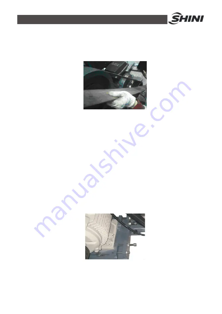
10) Adjust pulley: put a level bar in the middle of two pulleys, observe if mercury
column stays in the middle. If not, adjust pulleys to make them balanced.
11) Mount pulley, push motor to the right, twist adjusting screws to spread
forces on pulley evenly then tighten pulley and fasten adjusting bolts.
12) Mount motor shield and motor baffle.
Picture 3-7: Installation of Main Cutter Shaft and Bearing 3
Summary of Contents for SGS-6080S
Page 1: ...SGS S Single shaft Shredders Date May 2014 Version Ver B English...
Page 2: ......
Page 8: ...8 77...
Page 24: ...24 77 2 3 3 Cutting Chamber Structure Picture 2 8 Cutting Chamber Structure...
Page 31: ...31 77 2 3 12 Pushing Device Assembly Picture 2 12 Pushing Device Assembly...
Page 37: ...37 77 2 4 Wiring Diagram 2 4 1 Wiring Diagram Picture 2 16 Wiring Diagram...
Page 38: ...38 77 2 4 2 Control Wiring Diagram Picture 2 17 Control Wiring Diagram 1...
Page 39: ...39 77 Picture 2 18 Control Wiring Diagram 2...
Page 40: ...40 77 2 4 3 Electrical Components Layout Picture 2 19 Electrical Components Layout 1...
Page 41: ...41 77 Picture 2 20 Electrical Components Layout 2...


