background image


45(49) 


6.2  Components Maintenance 

6.2.1  Condenser 

A. Water-cooled series 
SIC-W-R2 series water chiller adopts tube-in-shell condenser which may have 
incrustations piled up in the inner side of its heat pipe or sundries caused by bad 
water  treatment.  All  these  will  influence  the  heat  emission  effect,  so  it  is 
necessary to clean the condenser at fixed periods to ensure its good working 
performance. 
If water treatment had been on to the cooling water, it is suggested that firstly 
use  hydrogen  peroxide  for  sterilization  and  then  use  high  pressure  air  rifle  to 
clean it and check whether there is still incrustation. If the cooling water had not 
be  put  under  the  water  treatment,  citric  acid  or  sulfamic  acid  together  with 
corrosion  inhibitor  is  suggested  to  clean  the  condenser,  after  that  use  high 
pressure  air  rifle  to  clean  it,  and  it  is  necessary  to  use  passivator  after  the 
acid-washing.   
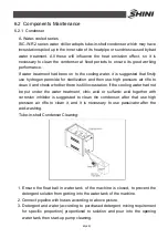
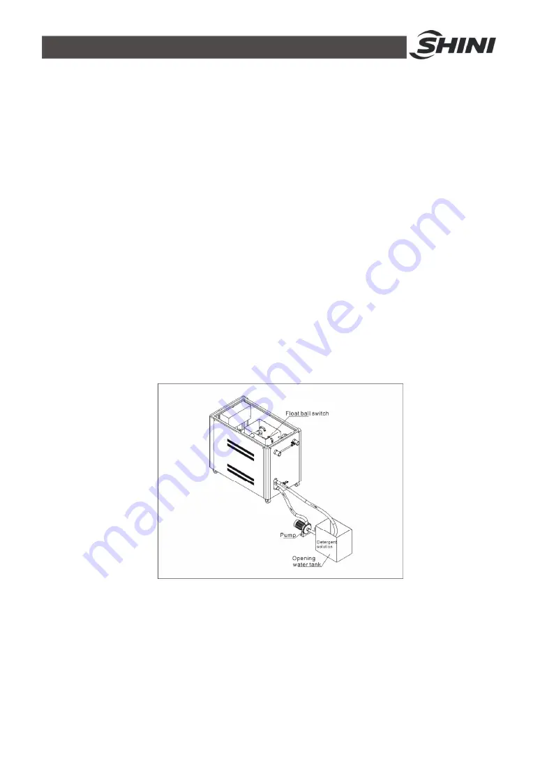
Tube-in-shell Condenser Cleaning


1.  Ensure  the  float  ball  in  water  tank  of  the  machine  is  closed,  to  prevent  the 

detergent solution from getting into the water tank of the machine.   

2. Connect pipeline with hoses according to above picture.   
3.  Detergent and  water  (according  to  purchased detergent mixing  requirement 

for  specific  proportion)  proportional  to  solution  and  pour  into  the  opening 
water tank, then start-up pump cleaning.   

Summary of Contents for SIC-A-R2

Page 1: ...SIC R2 Operation Manual of CFC free Refrigerant Water Chiller Date Jun 2017 Version Ver D English...

Page 2: ......

Page 3: ...ns 19 2 1 1 Working Principle 19 2 2 Main Parts and Functions 22 2 2 1 Compressor 22 2 2 2 Condensor 22 2 2 3 Drying Filter 23 2 2 4 Evaporator 23 2 2 5 High and Low Pressure Switch 24 2 2 6 Hot Air B...

Page 4: ...ing 36 6 Maintenance and Repair 40 6 1 Fill in the Refrigerant 44 6 2 Components Maintenance 45 6 2 1 Condenser 45 6 2 2 Evaporator 46 6 3 Maintenance Schedule 48 6 3 1 About the Machine 48 6 3 2 Chec...

Page 5: ...king Principle 20 Picture 2 3 Compressor 22 Picture 2 4 Condenser 22 Picture 2 5 Condenser 23 Picture 2 6 Drying Filter 23 Picture 2 7 Evaporator 23 Picture 2 8 Hot Air Bypass Valve 24 Picture 2 8 Liq...

Page 6: ...6 49...

Page 7: ...ompression circuit and equipped with compressor overload protection pump overload protection anti phase and open phase alarm anti freeze protection pressure controller which all ensure a stable and lo...

Page 8: ...h and low pressure switches to ensure stable operation Compressor and pump overload protection Adopt precise high precision temperature controller with an accuracy of 1 All adopt quality compressors f...

Page 9: ...tions for both handling and servicing Chapter 7 which contains service instructions intended for service engineers Other chapters contain instructions for the daily operator Any modifications of the m...

Page 10: ...ifications 1 3 1 External Dimensions SIC W R2 Series SIC 9W 42W R2 SIC 56W 84W R2 SIC 112W 132W R2 SIC A R2 Series SIC 7 5A R2 SIC 38A R2 SIC 48A R2 SIC 75A R2 SIC 100A R2 SIC 114A R2 Picture 1 1 Outl...

Page 11: ...2 210 SIC 14W R2 11 2 11 2 1 1 1 2 1 2 240 SIC 21W R2 11 2 11 2 11 2 11 2 1 2 1 2 330 SIC 28W R2 11 2 11 2 11 2 11 2 1 2 1 2 340 SIC 33W R2 2 2 2 2 1 2 1 2 430 SIC 42W R2 2 2 2 2 1 2 1 2 495 SIC 56W...

Page 12: ...12 49 SIC 75A R2 1942 755 1208 418 257 2922 21 2 21 2 1 1 2 1 2 840 SIC 100A R2 1942 641 1300 800 243 3475 21 2 21 2 1 1 1 1400 SIC 114A R2 1942 641 1300 900 255 3475 21 2 21 2 1 1 1 1600...

Page 13: ...Hz 3 3 3 7 4 5 3 1 3 5 4 3 2 8 3 9 5 7 2 7 3 3 4 0 2 7 3 7 4 7 2 6 3 5 4 5 3 2 4 4 3 1 4 1 3 4 4 1 2 8 3 8 3 7 4 4 3 2 4 3 60Hz 3 50 5 4 2 90 5 3 35 4 5 3 90 4 0 5 4 5 0 6 2 4 1 5 1 4 4 Total Power3 k...

Page 14: ...h Cooling Water Outlet 1 11 2 2 21 2 Water Tank Inlet 1 11 2 2 21 2 Water Tank Drainage Port 1 2 1 Water Tank Overflow Port 1 2 1 Protective Devices Compressor Overload relay Pump Overload relay Cooli...

Page 15: ...ter Tank Overflow Port 1 2 1 Protective Devices Compressor Overload relay Pump Overload relay Cooling Water Circuit High and low pressure switch anti freeze switch Water Circuit Flow switch Water leve...

Page 16: ...epairing the device be sure to turn off the main switch and control switch Warning High Voltage This label is posted on enclosure of the electrical control cabinet Warning Be careful Pay more attentio...

Page 17: ...he two electrical wires to solve this problem Pump pressure gauge display actual pressure of cold water system High pressure gauge display pressure in the high pressure side of refrigerant system Low...

Page 18: ...operation and maintenances upon machines without referring to the Manual prior to machine using 2 Any incidents beyond human reasonable controls which include man made vicious or deliberate damages o...

Page 19: ...arts working Refrigerant is compressed into high temperature and high pressure gas in the process from B to C and then be cooled when passing through the condenser and changed into liquid Heat is take...

Page 20: ...t is compressed into high temperature high pressure gas in the process form B to C and then be cooled when passing through condenser and changed into liquid Heat is taken away by the cooling air In th...

Page 21: ...s through by pass valve and then reaches evaporator balancing out part of the machine refrigerating capacity and then goes back to compressor without passing through condenser With the help of hot air...

Page 22: ...2 2 2 Condensor A Water cooled Series 1 Condenser is a heat output device which is used to discharge the heat absorbed by the evaporator and converted by the compressor to the cooling medium 2 SIC W...

Page 23: ...e of the filter is usually chosen according to the caliber of the cooling agent pipe 3 The dry filter is installed in front of the heat expansion valve to maintain the strictness of the valve Picture...

Page 24: ...than 40 bar or the pressure of the compressor suction port is lower than 5 bar 2 2 6 Hot Air Bypass Valve Picture 2 8 Hot Air Bypass Valve 1 Hot air by pass valve is used to bypass the cooling refrig...

Page 25: ...olenoid valve is used to cut the refrigerant supply immediately after the machine stops to prevent the compressor freezing 2 Solenoid vlave is installed in front of the refrigerant indicator 2 3 3 Ref...

Page 26: ...adopted to detect whether the chilled water flow is sufficient 2 Flow switch is installed on the water pipe between the evaporator and the water tank 2 3 5 Medium or high pressure pumps Medium and hi...

Page 27: ...and frequency corresponds with the requirements on manufacturer s name plate 2 Connection of the machine electrical wires and negative wire according to local rules and regulations 3 Use independent e...

Page 28: ...that main switch is turned off 3 3 Water connections A Water cooled Series Parts Name 1 Water chiller 2 Chilled water outlet 3 Chilled water inlet 4 Cooling water outlet 5 Cooling water inlet 6 Water...

Page 29: ...rigerated water pipe 2 Choose the suited cooling water tower according to the refrigerating capacity of the water chiller The specific information could consult the cooling tower supplier 3 The diamet...

Page 30: ...d the flow please refer to 1 3 Technical Specifications Cooling water pressure should be 2 5 4bar cooling water temperature is suggested at 25 35 8 Water used in the system must be processed since wat...

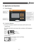
Page 31: ...4 2 Common Screens Commonly used screens include the main screen and the alarm screen 1 Main Screen The system will enter the main screen after countdown which displays as follows 2 Alarm Screen In c...

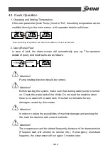
Page 32: ...ention Pump rotating direction should be correct Attention Before starting the system make sure that cooling water pump is turned on Check the water tank of the chiller Do not start the machine when t...

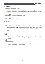
Page 33: ...e switch of compressor 2 Turn off the pump switch If it adopts the quick molding cycle and low cooling water temperature keep continuous running of water pump till the mould temperature rises to non c...

Page 34: ...ration For the modification operation of parameter value the user s modification of setting temperature will be described as an example 4 6 2 User Setting All the parameters in user settings please re...

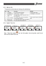
Page 35: ...dbus RTU 5 Machine Info To query the machine version information 6 Clock setting To query and set the system time 4 6 4 System Time Set System time set screen Save change and enter month System time s...

Page 36: ...ter temp Sensor breaks Check if the temperature probe is in proper contact Water temp Sensor short circuit Anti freeze Sensor breaks Anti freeze Sensor short circuit Anti freeze Temp Low Check if the...

Page 37: ...he pump Check if the antifreeze input is consistent with the switch setting Water temp Sensor breaks Check if the temperature probe is in proper contact Water temp Sensor short circuit Anti freeze Sen...

Page 38: ...compressor button has pressed If the LP Check Delay is not 0 then compressor 3 runs the test Compressor 3 overload Compressor 3 runs the test Compressor 4 pressure high Test when the compressor butto...

Page 39: ...for air cooled series Compressor 4 runs the test Check if the blower 4 fault input input is consistent with the switch setting Water flow short Test after the pump starts for Pump on delay time Stop...

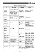
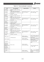
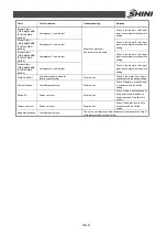
Page 40: ...40 49 6 Maintenance and Repair A Water cooled Series...

Page 41: ...41 49...

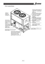
Page 42: ...42 49 B Air cooled Series...

Page 43: ...safely please caution the matter follows 1 Do not turn off the main power switch to stop the machine except emergency situation 2 When failures set in and the machine stop work with buzzer sound first...

Page 44: ...here s the leakage 2 Under no leakage circumstance it should use R410A special hose for filling that connects to vacuum pump The vacuumizing time should not less than 4h 3 After vacuumizing connect th...

Page 45: ...to clean it and check whether there is still incrustation If the cooling water had not be put under the water treatment citric acid or sulfamic acid together with corrosion inhibitor is suggested to c...

Page 46: ...ater to cascade the tray pipe Note do not let the water to cascade on the surface of the fan motor Attention Do the cleaning work every half year in the environment with little dust but you must do th...

Page 47: ...onal to solution and pour into the water tank of machine then start up pump cleaning of the machine 3 After discharging the bactericide solution when cleaning finished it should repeat more turns of w...

Page 48: ...ce of power supply 6 3 3 Daily Checking Check switch functions Check all the electrical wires Check whether pressure gauges are accurate Check whether compressor temperature is normal Check whether co...

Page 49: ...7 Half yearly Checking Check and clean the condenser and evaporator Check and clean the filter and expansion valve Check system performance Clean condenser 6 3 8 Yearly Checking Check whether the cont...

Reviews: