background image


41(49) 


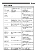
ON 07 MidMold Off 

2. Whether having the signal of middle mode 
in the monitor. 
3. Check I/O connecting wire. 
4. Whether having trouble on power board. 

Error Number 51 
06 R.Out LmtOFF 
05 R.In LmtOFF 

Out limit and in limit no signal input at 
the same time. 

1. When rotating in, check the indicator light 
of the rotary switch on or not. 
2. When rotating out, check the indicator light 
of the rotary switch on or not. 
3. Check I/O connecting wire. 
4. Whether having trouble on power board. 

Error Number 52 
Before descend 04 Main 
Clip ON 

Before arm descending, Main arm grip 
valve working. 

1. Whether having main grip, before arm 

descending, Main arm grip off. 

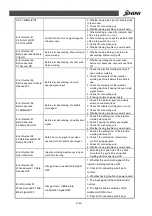
Error Number 54 
Before descend 
07 Vacuum ON 

Before arm descending, vacuum suck 
Valve working. 

1. Whether operating the vacuum suck, 

before arm descends, vacuum suck Valve 
off. 

Error Number 55 
Before descend 10 Mold 
OpenedOFF 

Before arm descending, no mold 
opened signal input. 

1. Check the injection molding machine if 

open mold completely. 

2. Check the computer of the injection 

molding machine if allows the robots to 
use. 

3. Check the computer of the injection 

molding machine if having the open mold 
signal output. 

4. Check I/O connecting wire. 
5. If having trouble on power board. 

Error Number 56 
Before descend 
07 MidMoldOff 

Before arm descending, No middle 
mold signal. 

1. Check if the indicator light of proximity 

switch on middle mold on. 

2. Check the middle mold signal on or not. 
3. Check I/O connecting wire. 
4. Whether having trouble on power board. 

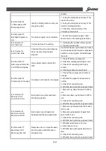
Error Number 57 
Before descend 
09 Safety DoorOFF 

Before arm descending, no safety door 
signal. 

1. Check if the safety door of the injection 

molding machine off. 

2. Check if having the safety door signal. 
3. Check I/O connecting wire. 
4. Whether having trouble on power board. 

Error Number 58 
09 Mold OpenedON 08 
Safety DoorOFF 

Safety door use, signal input when 
opened mold. No safety door signal. 

1. Check if the safety door of the injection 

molding machine off. 

2. Check if the safety door of electronic 

control having signaled. 

3. Check I/O connecting wire. 
4. Whether having trouble on power board. 

Error Number 59 
Open Wait Over 

Injection molding machine cycle open 
mold time too long. 

1. Extending the cycle time of the robots, 

more than the cycle time of injection 
molding machine opening mold. 

Error Number 60 
When descend 10 Mold 
Opened OFF 

Arm go down, opened mold signal 

OFF.


1. Whether the open mold signal of the 

injection molding machine OFF. 

2. Check I/O connecting wire if poor 

contact. 

3. Whether having trouble on power board.


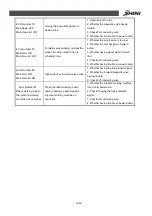
Error Number 61 

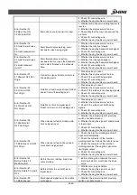
When descend 07 Mid. 

Mold signal OFF


Arm go down, middle plate 

confirmation signal OFF.


1. The input signal of the middle mold if 

normal. 

2. The light of sensor switches of the 

middle mold ON or not. 

3. Check I/O connecting wire if poor 

Summary of Contents for SS-S1

Page 1: ...SS S1 Standard Swing arm Robot 1 User Manual Date August 2017 Version V1 0 English...

Page 2: ...2 49...

Page 3: ...IONS UNIT MM 14 2 2 1 Model Specification 15 2 2 2 Pneumatic Source Requirement 15 2 3 ELECTRICAL CONNECTION 16 2 3 1 Main Power Supply 16 2 3 2 Interface with the Injection Molding Machine 16 2 4 AXE...

Page 4: ...RUCTIONS 31 4 1 HAND CONTROLLER 31 4 1 1 The Panel of Hand Controller 31 4 1 2 Keys 31 4 2 MANUALLY OPERATION 31 4 3 AUTOMATIC OPERATION 32 4 4 SYSTEM OPERATION 32 4 4 1 Stand by Mode 32 4 4 2 Languag...

Page 5: ...re 3 1 Shock Absorber on Crosswise 26 Picture 3 2 Handle 27 Picture 3 3 Pneumatic Protection Device 27 Picture 3 4 Emergency Stop Button 28 Picture 3 5 Robot Base 29 Picture 3 6 Filter Regulator 29 Pi...

Page 6: ...6 49...

Page 7: ...r use beyond the user manual the manufacturer will not have any responsibility 1 2 Safety Concerns The maintenance repair etc must be executed by professionally trained personnel Any unrelated personn...

Page 8: ...purpose Electrical system If not comply with safety recommendations as described in the electrical system symbols will result in an electric shock personnel occur The safeguarding required for operati...

Page 9: ...9 49 1 3 The Warning Marks and Its Meanings No Marks Meaning 1 Do Not Touch 2 Caution danger 3 Caution Electric shock 4 Caution Mechanical injury 5 Caution High temperature 6 No Flame...

Page 10: ...lease enquire for assistance from the manufacturer or agents If you do not comply with this mandatory requirement result in the injury to any personnel and equipment the robot manufacturer will not ha...

Page 11: ...long time anti rust of the robot and if necessary place film to prevent dust and rain water corrosion 1 5 3 Unpacking Transportation 1 Use a special strap and hook cotton non slip strap the min load 8...

Page 12: ...atment 1 6 Exemption Clause The following statements clarify the responsibilities and regulations born by any buyer or user who purchases products and accessories from Shini including employees and ag...

Page 13: ...tween the gas source and the filter Note Before connecting hoses clean the hose by compressed air To ensure that there is no cuttings seal tapes and so on in the hose 2 Check the compressed air connec...

Page 14: ...tions 4 Place electrical drill with magnet base on the fixing plate use 8 5 drill bits to drill 6 holes about 30mm depth 5 Use M10 tap to produce 6 internal screw threads about 25mm depth 2 1 6 Mounti...

Page 15: ...1200 1250 B 320 C 820 D 100 Outlook Dimension mm E 430 Note 1 V stands for vacuum device M stands for middle mold detector suitable for three plate mold EM12 stands for Euromap 12 communication interf...

Page 16: ...ting of all signals must be done by a specialist in injection molding machines and robots Preferably this should be done by one of our service engineers together with a qualified service engineer for...

Page 17: ...be adjusted Adjusting the end position 1 Run the X axis to its end position 2 Push the axis to the desired position manually 3 Fix the stop package Adjusting the 0 position stroke length 5 Run the X a...

Page 18: ...position of the shock absorber Before adjusting release the compressed air 1 Loosen the nuts on the rotate cylinder 2 Adjust the rotate cylinder into the desired position 3 Tighten the nuts in place...

Page 19: ...picks parts the light of magnetic switch on if gripper hasn t picks parts the light off 3 Tighten the fixing screw after finishing adjustment During the robot operation if the gripper not clamps the p...

Page 20: ...ol is open and must remain HIGH at least until close tool enabled see pin contact No A6 ZA6 Mold closed HIGH signal when tool closing has been completed the signal close tool enabled is no longer nece...

Page 21: ...osition before it is moved into the tool area If the switch is open neither a closing nor opening motion of the tool may take place Even when the control system of the robot is shut off the switch mus...

Page 22: ...r removal of the molding When the motion of the core pullers is to the position for removal of the molding is enabled B7 Optional Enable movement of core pullers 2 to position for the robot to approac...

Page 23: ...el in Switch see pin contact No 16 is closed when the core pullers regardless of the position of the movable tool plate are in position for free travel in of the robot 7 Optional Core pullers in posit...

Page 24: ...signal is given by injection molding machine see contact No 4 22 Enable ejector forward The switch contact see pin contact No 32 is closed when the handing device enable the movement for ejector forw...

Page 25: ...ed appearance Swing directions are moving directions in order to provide safety mechanically and electrically Fast mold changing design provides simple method for changing molds The base is rotatable...

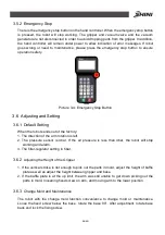
Page 26: ...c hand controller provides English Japanese Traditional Chinese and Simplified Chinese Other languages are applicable There are 8 standard programs and memory for up to 80 customized programs with sel...

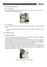
Page 27: ...m falling when air pressure is not enough If the air pressure is not enough the sensor will output the signal The robot s arm keeps in current position or returns to the up limit position then the pne...

Page 28: ...ctory 1 The direction of the arm rotation is left 2 The pressure sensor is 4bar If the air pressure is less than 4bar the robot will stop working and alarm 3 The filter regulator setting in 5bar 3 6 2...

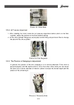
Page 29: ...fitting Adjust the air flow to change the speed of the drive cylinder Picture 3 6 Filter Regulator 3 6 5 The Position of Swinging in Adjustment In general the position of the arm swinging in is in ver...

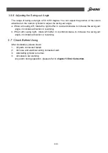
Page 30: ...to increase the swing out angle in clockwise direction is reversing b When arm swing right rotate left buffer in counterclockwise to increase the swing out angle in clockwise direction is reversing 3...

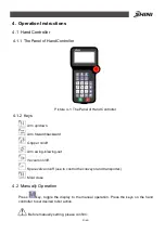
Page 31: ...rm up down Arm forward backward Gripper on off Arm swing in swing out Vacuum on off Spare valve on off use to control the conveyor and transporter Mold close 4 2 Manually Operation Press key toggle th...

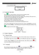
Page 32: ...t action is physically time use Note if robot or IMM alarm but robot should keep auto running press AUTO key to turn off the alarm If press STOP key robot will back to home position and stop auto runn...

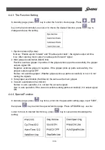
Page 33: ...Negative examine gripper in negative If the gripper picks up parts successfully the gripper outputs signal OFF NoUse not examine gripper Whether gripper picks up parts successfully or not it is not te...

Page 34: ...auto mode the arms wait outside for next cycle and then rotate inside before the module program action 6 Key sound Sound Off No sound while pressing On Sound while pressing 7 Products number cleared P...

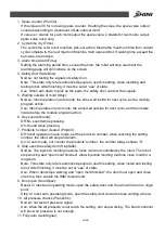
Page 35: ...the setting 4 4 6 Mold Set To copy the mold recipe press key twice to enter into copy molds page The user can choose one program from 0 99 to read it and then put it into 20 99 to memory as the code...

Page 36: ...l molds action begins from original point and at the end of the cycle back to it otherwise the action program is incomplete and robot cannot operate in auto mode Original point actions 1 Arm upgoing 2...

Page 37: ...e quantity 0001 open mold delay 0002 ejection delay 0003 the main arm down 0004 the main arm forward 0005 the main arm clip 0006 main arm backward 0007 main arm up 0008 rotate outside 0009 the main ar...

Page 38: ...side 0500 produce quantity 0501 open mold delay 0502 ejection delay 0503 main arm down 0504 main arm forward 0505 vacuum absorb 0506 the main arm clip 0507 main arm backward 0508 main arm up 0509 rota...

Page 39: ...ving trouble on power board Error number 04 05 Vacuum ON 04 Suck lmt OFF The sucker working and the vacuum suck no signal input 1 Whether the air pressure is too low 2 Check if sucker suck the product...

Page 40: ...low 3 Check if the rotation in limit having signals 4 Check I O connecting wire 5 Whether having trouble on power board Error Number 33 06 R Out Lmt ON Not Origin Rotation out limit no signal input R...

Page 41: ...cending No middle mold signal 1 Check if the indicator light of proximity switch on middle mold on 2 Check the middle mold signal on or not 3 Check I O connecting wire 4 Whether having trouble on powe...

Page 42: ...nput or not 3 Check I O connecting wire if poor contact 4 If having trouble on power board Error Number 74 Air pressure not enough Air pressure of robots is not enough 1 Check if the air pressure of r...
Page 43: ...gnal when forward limit 4 Check I O connecting wire 5 Whether having trouble on power board Error Number 80 MainForw OFF MainForw lmt ON Signal input no forward valve action 1 Whether having the forwa...

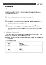
Page 44: ...in particular that safety instructions marked with a must be observed according to regulations so that fully functionality of this equipment can be guaranteed 6 2 Lubrication Requirements Remove the o...

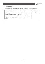
Page 45: ...er drainage 3 Check the pressure of air supply 4 Check bolt which connected the robot and injection molding machine whether tighten 5 Check all block settings whether tightened 1 Use air gun to clean...

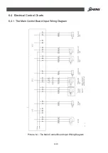
Page 46: ...46 49 6 4 Electrical Control Charts 6 4 1 The Main Control Board Input Wiring Diagram Picture 6 1 The Main Control Board Input Wiring Diagram...

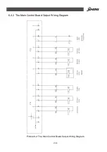
Page 47: ...47 49 6 4 2 The Main Control Board Output Wiring Diagram Picture 6 2 The Main Control Board Output Wiring Diagram...

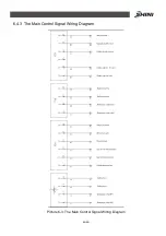
Page 48: ...48 49 6 4 3 The Main Control Signal Wiring Diagram Picture 6 3 The Main Control Signal Wiring Diagram...

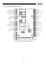
Page 49: ...49 49 6 4 4 The Main Control Panel Layout Picture 6 4 The Main Control Panel Layout...

Reviews: