19(147)
system works in normally.
4. Before installation, wiring, operation, and maintenance must be familiar
with instructions guide as well as machinery, electronics and security
attentions.
5. Ground the wire before robot operating.
6. Wire grounding should connect to metal and keep away from inflammable
matter.
The power requirements are given on the type plate of the robot, the power
connection is provided through a normal power cord and a CEE plug.
The power connection should be performed only by authorized
electrician and should be in accordance with any applicable
regulations.
2.1.4 Safety Fence
1. After installing the robot, indicate the safety fence outside the scope of the
robot working area.
2. The hand controller should be fixed outside of the safety fence.
3. Stick the warning signals on outstanding place of the fence.
2.1.5 Mounting Preparation
1. Before drilling, switch off the injection molding machine and then turn off
the power, avoid the scrap-iron into the mold.
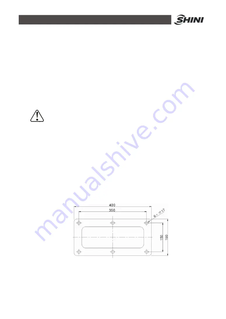
2. Stick the drilling picture on the installing surface of IMM.
3. Use the center punch to assist drilling.
4. Place the magnetic drill on the fixing plate, use drill bits (
Ф
14) to drill 6
Summary of Contents for ST1-1100-1800
Page 1: ...ST1 Single Axis Servo Driven Robot User Manual Date May 2016 Version V1 4 English ...
Page 2: ......
Page 46: ...46 147 Picture 2 3 X025 sensor Picture 2 4 X 025 lights up ...
Page 76: ...76 147 7 Assembly Diagram 7 1 Traverse Unit ST1 and ST1 T Picture 7 1 ...
Page 88: ...88 147 7 2 Vertical Unit ST1 Picture 7 2 ...
Page 93: ...93 147 7 3 Main arm unit ST1 Picture 7 3 ...
Page 98: ...98 147 7 4 Sub Arm unit ST1 Picture 7 4 ...
Page 101: ...101 147 7 5 Main Arm ST1 T Picture 7 5 ...
Page 104: ...104 147 7 6 Sub arm ST1 T Telescopic Arm Picture 7 6 ...
Page 107: ...107 147 7 7 Vertical ST1 T Telescopic Arm Picture 7 7 ...
Page 110: ...110 147 7 8 Traverse unit ST1 T Middle Telescopic Arm Picture 7 8 ...
Page 115: ...115 147 7 9 Main Arm ST1 T Middle Telescopic Arm Picture 7 9 ...
Page 120: ...120 147 7 10 Sub arm ST1 T Middle Telescopic Arm Picture 7 10 ...
Page 125: ...125 147 7 11 Crosswise Unit ST1 T Middle Telescopic Arm Picture 7 11 ...
Page 129: ...129 147 8 Electric Control Chart 8 1 The Power Input Wiring Diagram Picture 8 1 ...
Page 130: ...130 147 8 2 Main Control Panel and I O Wiring Diagram Picture 8 2 ...
Page 131: ...131 147 8 3 Panasonic Servo Motor Wiring Diagram 1 Picture 8 3 ...
Page 132: ...132 147 8 4 Panasonic Servo Motor Wiring Diagram and Spare Wiring Diagram M1 3 Picture 8 4 ...
Page 133: ...133 147 8 5 YASKAWA Servo Motor Wiring Diagram 1 Picture 8 5 ...
Page 134: ...134 147 8 6 YASKAWA Servo Motor Wiring Diagram and Spare Wiring Diagram M1 3 Picture 8 6 ...
Page 135: ...135 147 8 7 Z axis Wiring Diagram Picture 8 7 ...
Page 136: ...136 147 8 8 Main Arm Wiring Diagram 1 Picture 8 8 ...
Page 137: ...137 147 8 9 Main Arm Wiring Diagram 2 Picture 8 9 ...
Page 138: ...138 147 8 10 Sub Arm Wiring Diagram Picture 8 10 ...
Page 139: ...139 147 8 11 EM67 Signal Input Wiring Diagram Picture 8 11 ...
Page 140: ...140 147 8 12 EM67 Signal Output Wiring Diagram Picture 8 12 ...
Page 141: ...141 147 8 13 Main Control Board Component Layout Picture 8 13 ...
Page 142: ...142 147 8 14 I O U2 Board Component Layout 0 Picture 8 14 ...
Page 144: ...144 147 8 16 Main Arm U4 Layout Picture 8 16 ...
Page 145: ...145 147 8 17 Sub arm U5 Component Layout Picture 8 17 ...
Page 147: ...147 147 ...


