71(147)
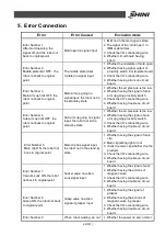
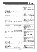
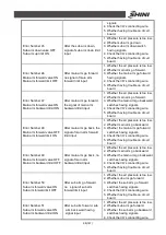
Error Number 68
Up to set production
Current production has
reached the setting
1. Increase values of yield.
2. Clear the current yield.
Error Number 69
Action not according with the
program
Manual to move arm up
/down inside not according
with the automatic
program
1. Manual operation make arm rise
inside and fall in forward or
backward position which
corresponding automatic process,
otherwise may damage the mold.
Error Number 70
The time of waiting open
mould delay
The time of the IMM open
mould cycle is too long
1. Lengthen the cycle time of
electronic control of robot, and
make the time longer than that of
open mold of injection molding
machine.
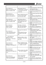
Error Number 71
Servo-drive failure, no pulse
input
Electric receive servo drive
feedback pulse or not
1. Check servo drive setting
parameter.
2. Check servo drives and electric
control connecting.
3. Check setting parameter of electric
control.
4. Whether having trouble on circuit
board.
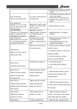
Error Number 72
Servo driven alarm
Servo driven alarm
1. Check whether the servo driven
alarm.
2. Check servo driven and electric
control connecting.
3. Whether having trouble on circuit
board.
Error Number 73
The position of the safety
door not set
The position of the safety
door not set
1. Set the position of the safety door.
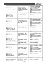
Error Number 74
The position of the placing
lower than that of safe door
Setting the position of the
placing lower than that of
safe door
1. Reset the position of the place, the
position must be higher than safe
door.
Error Number 75
The position of the placing
goods is more than the
maximum
The position of the placing
goods is set more than the
maximum
1. Reset the position of the placing
goods, make it less than the
maximum.
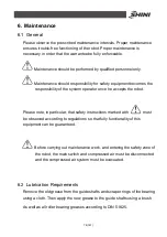
Error Number 76
Outside waiting position is
less than the initiation value
position
The outside waiting position
is less than the initiation
position
1. Reset the outside waiting position,
must more than the initiation
position.
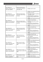
Error Number 77
The position of the placing
goods is more than the
maximum
The outside waiting position
is more than the maximum
1. Reset the outside waiting position,
must more than the maximum.
Error Number 78
Points of cycle placing
position is more than safe
limits
Maximum of Cycle placing
position is more than safe
limits
1. Reset points of cycle placing or
distance of cycle placing.
Error Number 79
Travel out limit is abnormal
The travel out limit switch
has no signal input
1. Check whether having the signal of
the limit switches.
2. Check the I/O
’
s connecting wire.
Summary of Contents for ST1-1100-1800
Page 1: ...ST1 Single Axis Servo Driven Robot User Manual Date May 2016 Version V1 4 English ...
Page 2: ......
Page 46: ...46 147 Picture 2 3 X025 sensor Picture 2 4 X 025 lights up ...
Page 76: ...76 147 7 Assembly Diagram 7 1 Traverse Unit ST1 and ST1 T Picture 7 1 ...
Page 88: ...88 147 7 2 Vertical Unit ST1 Picture 7 2 ...
Page 93: ...93 147 7 3 Main arm unit ST1 Picture 7 3 ...
Page 98: ...98 147 7 4 Sub Arm unit ST1 Picture 7 4 ...
Page 101: ...101 147 7 5 Main Arm ST1 T Picture 7 5 ...
Page 104: ...104 147 7 6 Sub arm ST1 T Telescopic Arm Picture 7 6 ...
Page 107: ...107 147 7 7 Vertical ST1 T Telescopic Arm Picture 7 7 ...
Page 110: ...110 147 7 8 Traverse unit ST1 T Middle Telescopic Arm Picture 7 8 ...
Page 115: ...115 147 7 9 Main Arm ST1 T Middle Telescopic Arm Picture 7 9 ...
Page 120: ...120 147 7 10 Sub arm ST1 T Middle Telescopic Arm Picture 7 10 ...
Page 125: ...125 147 7 11 Crosswise Unit ST1 T Middle Telescopic Arm Picture 7 11 ...
Page 129: ...129 147 8 Electric Control Chart 8 1 The Power Input Wiring Diagram Picture 8 1 ...
Page 130: ...130 147 8 2 Main Control Panel and I O Wiring Diagram Picture 8 2 ...
Page 131: ...131 147 8 3 Panasonic Servo Motor Wiring Diagram 1 Picture 8 3 ...
Page 132: ...132 147 8 4 Panasonic Servo Motor Wiring Diagram and Spare Wiring Diagram M1 3 Picture 8 4 ...
Page 133: ...133 147 8 5 YASKAWA Servo Motor Wiring Diagram 1 Picture 8 5 ...
Page 134: ...134 147 8 6 YASKAWA Servo Motor Wiring Diagram and Spare Wiring Diagram M1 3 Picture 8 6 ...
Page 135: ...135 147 8 7 Z axis Wiring Diagram Picture 8 7 ...
Page 136: ...136 147 8 8 Main Arm Wiring Diagram 1 Picture 8 8 ...
Page 137: ...137 147 8 9 Main Arm Wiring Diagram 2 Picture 8 9 ...
Page 138: ...138 147 8 10 Sub Arm Wiring Diagram Picture 8 10 ...
Page 139: ...139 147 8 11 EM67 Signal Input Wiring Diagram Picture 8 11 ...
Page 140: ...140 147 8 12 EM67 Signal Output Wiring Diagram Picture 8 12 ...
Page 141: ...141 147 8 13 Main Control Board Component Layout Picture 8 13 ...
Page 142: ...142 147 8 14 I O U2 Board Component Layout 0 Picture 8 14 ...
Page 144: ...144 147 8 16 Main Arm U4 Layout Picture 8 16 ...
Page 145: ...145 147 8 17 Sub arm U5 Component Layout Picture 8 17 ...
Page 147: ...147 147 ...


