59(178)
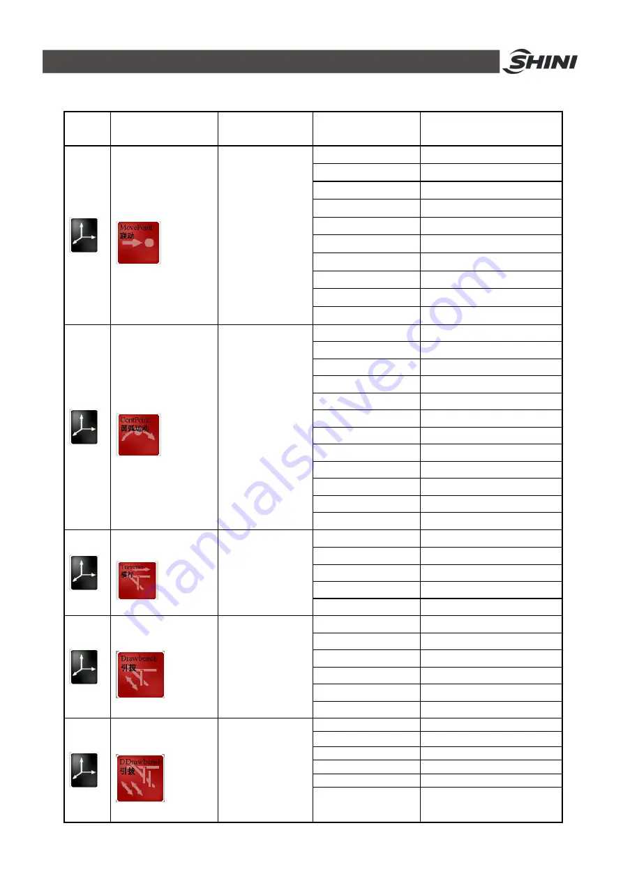
Table 4-1: Servo motor commands list
Group
Command/
Schematic
Function
Parameter
Unit
terminal point on axis 1 mm/Inch
terminal point on axis 2 mm/Inch
terminal point on axis 3 mm/Inch
terminal point on axis 4 mm/Inch
terminal point on axis 5 mm/Inch
speed
% relative to max.speed
acceleration
% relative to max acceleration
deceleration
% relative to max deceleration
Interval position
mm/Inch
Linkage
All
linear
axes
Direct move to the
set corresponding
position
Safety time
S (moving monitor time
)
terminal point on axis 1 mm/Inch
terminal point on axis 2 mm/Inch
terminal point on axis 3 mm/Inch
terminal point on axis 4 mm/Inch
terminal point on axis 5 mm/Inch
S radian
mm/Inch
P2 position 1
-
(
select radian direction
)
speed
% relative to max speed
acceleration
% relative to max acceleration
deceleration
% relative to max deceleration
Interval position
mm/Inch
S-linkage
All linear axes
achieve S linkage
Safety time
S (moving monitor time
)
Final position
mm/Inch
speed
% relative to max speed
acceleration
% relative to max acceleration
deceleration
% relative to max deceleration
Z-axis operation
Z-axis run to
absolute position
Safety time
S (moving monitor time
)
Arm selection
Main arm/Sub arm
Final position
mm/Inch
speed
% relative to max speed
acceleration
% relative to max acceleration
deceleration
% relative to max deceleration
X-axis 1 operation
X-axis 1 run to
absolute position
Safety time
S (moving monitor time
)
Axis-X Final position
mm/Inch
Axis-X2 Final position
mm/Inch
speed
% relative to max speed
acceleration
% relative to max acceleration
deceleration
% relative to max deceleration
X-axis 2 operation
X-axis 2 run to
absolute position
Safety time
S (moving monitor time
)
Summary of Contents for ST3 Series
Page 1: ...ST3 5 Fully Servo Driven Robot User Manual Date Jun 2016 Version V1 5 English ...
Page 2: ...2 178 ...
Page 12: ...12 178 ...
Page 121: ...121 178 7 9 ST3 MT Traverse unit Fig 7 11 ST3 MT traverse unit exploded view ...
Page 123: ...123 178 7 10 ST3 MT Crosswise Unit Fig 7 12 ST3 MT crosswise Unit exploded view ...
Page 125: ...125 178 7 11ST3 MT Main arm unit Fig 7 13 ST3 MT Main arm unit telescopic arm exploded view ...
Page 130: ...130 178 7 13 ST3 LT Crosswise Unit Fig 7 15 ST3 LT crosswise unit exploded view ...
Page 132: ...132 178 7 14 ST3 LT Main arm unit Fig 7 16 ST3 LT main arm unit exploded view ...
Page 150: ...150 178 9 15 ST3 SIGMATEK module board Fig 9 15 ST3 SIGMATEK Module board 1 ...
Page 151: ...151 178 Fig 9 16 ST3 SIGMATEK Module board 2 ...
Page 174: ...174 178 10 19 ST5 SIGMATEK module board Fig 10 21 ST5 SIGMATEK module board 1 ...
Page 175: ...175 178 Fig 10 22 ST5 SIGMATEK module board 2 ...


