81(178)
1) Set homing sequence
Total 8 axes can set 6 levels homing sequence
2) Choose reference point
Can choose none or reference point
3) Set each axes origin offset
After all axes are back to the home position, if there is deviation from the ideal position, the
home position offset setting can make it back to ideal position. Servo axis
’
s position offset
unit is mm; pneumatic axis
’
s position offset can choose from none, maximum value and
minimum value.
4.3.8.2 Axis Configuration
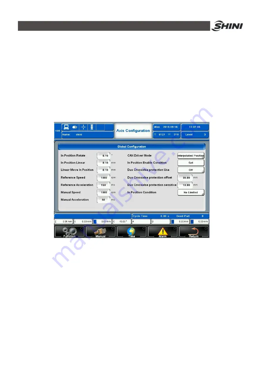
Click
Function--Servo Setup--Axis
Configuration to enter the page as shown in Fig.4-48.
Fig.4-48: Axis configuration page
1) In Position Rotate
It is set as the minimum deviation angle to determine whether the axis is in the position, the
operation unit is degree. For example, to rotate 30
°
, we set the minimum deviation angle as
0.10
°
, then when the servo axis rotate to 29.90
°
, the system will consider the axis is in the
position.
2) In Position Linear
Set the minimum deviation distance to determine whether the axis is in the position,the
operation unit is mm. For example, to move 30mm, set the value as 0.10mm, then when the
servo axis move to 29.90mm, the system will consider the axis is in the position.
3) Reference Speed
Motor speed when going back to the origin. Unit : RPM
Summary of Contents for ST3 Series
Page 1: ...ST3 5 Fully Servo Driven Robot User Manual Date Jun 2016 Version V1 5 English ...
Page 2: ...2 178 ...
Page 12: ...12 178 ...
Page 121: ...121 178 7 9 ST3 MT Traverse unit Fig 7 11 ST3 MT traverse unit exploded view ...
Page 123: ...123 178 7 10 ST3 MT Crosswise Unit Fig 7 12 ST3 MT crosswise Unit exploded view ...
Page 125: ...125 178 7 11ST3 MT Main arm unit Fig 7 13 ST3 MT Main arm unit telescopic arm exploded view ...
Page 130: ...130 178 7 13 ST3 LT Crosswise Unit Fig 7 15 ST3 LT crosswise unit exploded view ...
Page 132: ...132 178 7 14 ST3 LT Main arm unit Fig 7 16 ST3 LT main arm unit exploded view ...
Page 150: ...150 178 9 15 ST3 SIGMATEK module board Fig 9 15 ST3 SIGMATEK Module board 1 ...
Page 151: ...151 178 Fig 9 16 ST3 SIGMATEK Module board 2 ...
Page 174: ...174 178 10 19 ST5 SIGMATEK module board Fig 10 21 ST5 SIGMATEK module board 1 ...
Page 175: ...175 178 Fig 10 22 ST5 SIGMATEK module board 2 ...


