83(178)
2) Axis configuration window
There are two parts to be set in this window, control parameters and servo parameters. The
parameters details are as shown in the table below.
Table 4-4: Axis configuration details
Control parameter configuration
Arm number
[-]
Single/ double
Motor direction
[-]
Set moving direction
Pitch
mm
Set Synchronous Wheel parameter
Tooth number
[-]
Set Synchronous Wheel parameter
Gear ratio
[-]
Set gear ratio
KV
1/s
Position gain
VU
[-]
Speed gain
Maximum Drag limit
mm
The maximum deviation between command speed and
actual speed. If the value exceed the maximum deviation,
system will alarm, servo position overrun
Servo parameter configuration
Software
minimum
position
mm
Minimum position allowed, recommend to set at -1.00
Software
maximum
position
mm
Maximum position allowed, depend on machine
dimensions
Motor speed
RPM
Set motor rated rotation speed. Please set the value on the
motor nameplate
Vmax
[-]
Calculated by motor speed automatically, user no need to
calculate
Amax
mm/s
2
Maximum acceleration of the motor accelerating from static
to the desired speed
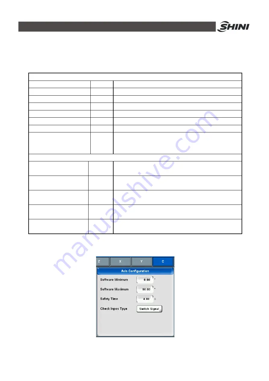
The configuration of pneumatic axes as shown in Fig.4-50 and its details as shown in table
4-5.
Fig.4-50: Axis configuration window
Summary of Contents for ST3 Series
Page 1: ...ST3 5 Fully Servo Driven Robot User Manual Date Jun 2016 Version V1 5 English ...
Page 2: ...2 178 ...
Page 12: ...12 178 ...
Page 121: ...121 178 7 9 ST3 MT Traverse unit Fig 7 11 ST3 MT traverse unit exploded view ...
Page 123: ...123 178 7 10 ST3 MT Crosswise Unit Fig 7 12 ST3 MT crosswise Unit exploded view ...
Page 125: ...125 178 7 11ST3 MT Main arm unit Fig 7 13 ST3 MT Main arm unit telescopic arm exploded view ...
Page 130: ...130 178 7 13 ST3 LT Crosswise Unit Fig 7 15 ST3 LT crosswise unit exploded view ...
Page 132: ...132 178 7 14 ST3 LT Main arm unit Fig 7 16 ST3 LT main arm unit exploded view ...
Page 150: ...150 178 9 15 ST3 SIGMATEK module board Fig 9 15 ST3 SIGMATEK Module board 1 ...
Page 151: ...151 178 Fig 9 16 ST3 SIGMATEK Module board 2 ...
Page 174: ...174 178 10 19 ST5 SIGMATEK module board Fig 10 21 ST5 SIGMATEK module board 1 ...
Page 175: ...175 178 Fig 10 22 ST5 SIGMATEK module board 2 ...


