95(178)
4.5 Alarms and Logs
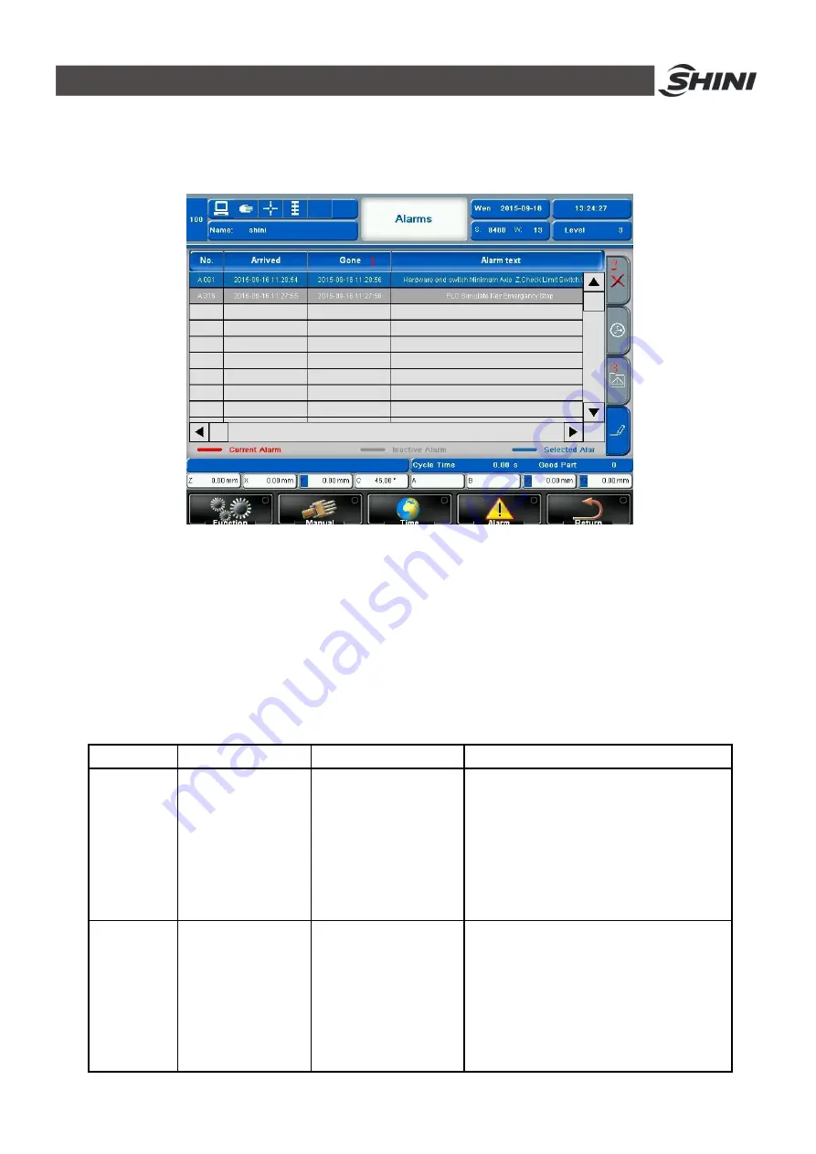
Click Alarm to enter the page as shown in Fig.4-66.
Fig.4-66: Alarm page
1) Alarm information details. Including alarm sequences, alarm trigger time and date, alarm
response time and date and description of the alarm details information
2) Clear the responded alarms. If the alarm has already been responded, then all the
responded alarms can be deleted in the list.
3) Enter the operating record page
4) See Table 4-6 alarm message instruction.
Table 4-6:
Alarm details
No
Alarm
Description
Solution
A 004 to
A 011
Servo Axis** internal
minimum distance
**is
(
X/Y/Z/A/B/C/Y2/Z2
)
total 8 axes
Current**axis
’
s
actual
position smaller than set
minimum position
In the manual page, move the axis to the
range of minimum position
Function/Servo Setup/ Servo operation
parameter configuration/**/Servo parameter
configuration -> software minimum position,
actual position need to greater than this value,
recommend to set at -1.00mm
A 012 to
A 019
Servo Axis** internal
maximum distance
**is
(
X/Y/Z/A/B/C/Y2/Z2
)
total 8 axes
Current**axis
’
s
actual
position greater than
set maximum position
In the manual page, move the axis to the
range of maximum position
Function/Servo Setup/ Servo operation
parameter configuration/**/Servo parameter
configuration -> software maximum position,
actual position need to greater than this value,
depend on machine dimensions
Summary of Contents for ST3 Series
Page 1: ...ST3 5 Fully Servo Driven Robot User Manual Date Jun 2016 Version V1 5 English ...
Page 2: ...2 178 ...
Page 12: ...12 178 ...
Page 121: ...121 178 7 9 ST3 MT Traverse unit Fig 7 11 ST3 MT traverse unit exploded view ...
Page 123: ...123 178 7 10 ST3 MT Crosswise Unit Fig 7 12 ST3 MT crosswise Unit exploded view ...
Page 125: ...125 178 7 11ST3 MT Main arm unit Fig 7 13 ST3 MT Main arm unit telescopic arm exploded view ...
Page 130: ...130 178 7 13 ST3 LT Crosswise Unit Fig 7 15 ST3 LT crosswise unit exploded view ...
Page 132: ...132 178 7 14 ST3 LT Main arm unit Fig 7 16 ST3 LT main arm unit exploded view ...
Page 150: ...150 178 9 15 ST3 SIGMATEK module board Fig 9 15 ST3 SIGMATEK Module board 1 ...
Page 151: ...151 178 Fig 9 16 ST3 SIGMATEK Module board 2 ...
Page 174: ...174 178 10 19 ST5 SIGMATEK module board Fig 10 21 ST5 SIGMATEK module board 1 ...
Page 175: ...175 178 Fig 10 22 ST5 SIGMATEK module board 2 ...


