EinScan HX User Manual
45
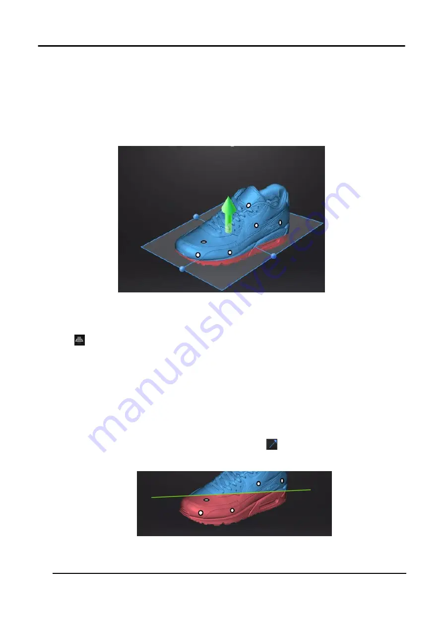
3.4.2 Create a Cutting Plane
The plane can be rotated, zoom or move.
Taking the model below as a reference, after setting the cutting plane, the cutting plane above the
direction of the arrow is valid (displayed in blue). The user can choose whether to save the data in
the reverse direction (displayed in red) or delete it. Although the data in the reverse direction of the
arrow can also be saved, the newly scanned data cannot be added to it.
Figure 3-30 Example
Steps
1.
Click
to enter cutting-plane interface.
2.
Choose a create method
Create a cutting plane by fitting point cloud
Press down Shift and Left mouse button to select point cloud data, those selected data is to
form a cutting plane.
Create cutting plane by straight line
Press down Shift and Left mouse button and then click
to draw a straight line on the
scanned object, a cutting plane generates from the line is created manually at the same time.
Figure 3-31 Straight Line Cutting Plane
Summary of Contents for EinScan HX
Page 25: ...EinScan HX User Manual 24 Figure 3 12 Different Ways of Sticking Markers ...
Page 27: ...EinScan HX User Manual 26 3 2 3 Workflow ...
Page 41: ...EinScan HX User Manual 40 Table 3 9 Preview Too bright X Good ...
Page 54: ...EinScan HX User Manual 53 Figure 3 39 Manual Marker Alignment ...
Page 57: ...EinScan HX User Manual 56 4 Click Apply to mesh ...
Page 83: ...EinScan HX User Manual 82 ...


