35
4 Function setting
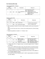
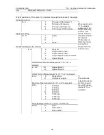
The following are commands equivalent to the functions on the indicator. To use functions
not specified in the following table, connect an indicator and set the function.
Command body
Code
Description
Equivalent
functions on the
indicator
Body
Breakpoint Numerics
C1
C2
C3
C4
C1
C2
C3
C4
F
0
,
0–5
46H 30H 2CH
30H
–
39H
Auto zero
1. A.0
0–5
F
1
,
1–8
46H 31H 2CH
Range for determining
stability
2A. S.H. 1–8
F
2
,
1–6
46H 32H 2CH
Number of times
stability is determined
2b. S.C. 1–6
F
3
,
0–7
46H 33H 2CH
Number of times
moving average is
calculated
3A. rE.
0–7
F
4
,
1–4
46H 34H 2CH
Processing signal
3C. Fr.
1–4
F
5
,
1–4
46H 35H 2CH
Weight update rate
3b. ti.
1–4
F
6
,
1–5
46H 36H 2CH
Specifying the
readability
62. d.A.
1–5
Response descriptions
A00: Normal termination
E01: Command error
E02: The numerics are out of scope or none
* Command bodies and numerics are divided by “,” (2CH).
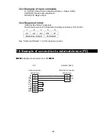
8-4-3 Examples of input commands
T
(CR)(LF)
Executing zero adjustment/tare (
: Space (20H))
C3(CR)(LF)
Begin span adjustment
O1(CR)(LF)
Begin continuous output
F0,2(CR)(LF)
Setting the operable range of auto zero to
±
1d
F1,6(CR)(LF)
Setting the range for determining stability to 8d
F6,4(CR)(LF)
Setting the readability to 0.01 g
8-4-4 Response format
“A00 and Exx format” responses
This format consists of 5 characters including the terminators (CR and
LF).
1
2
3
4
5
A1
A2
A3
CR
LF
Response content
Terminator
See “Command formats” 1,2 and 3 for response content.
Summary of Contents for UD-1
Page 52: ...48 Appendix 3 Outlines Weight measuring sensor UF 620 UF 3200 ...
Page 53: ...49 Indicator ...
Page 54: ......
Page 55: ...はくし ...
Page 56: ...はくし ...


