38
9-2 Assigning ID numbers to the weight measuring
sensors
To set an ID number, operate the dip switches built in the weight measuring sensor.
Remove the cover from the weight measuring sensor.
Use an Allen wrench to remove the four screws shown in the following figure and
remove the cover. Do not remove any screws other than those specified in the figure.
Since the cover is connected to the main unit via board wiring through a cable, these
cannot be completely separated. Be careful not to cut the cable by pulling the cover too
far away.
Operate the dip switches to assign an ID number.
When the cover is removed, dip switches can be seen that are used to set an ID
number at rear of the main unit.
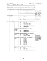
Refer to the following table to set an ID number by using a thin rod.
Be careful not to damage the board and cable during setting.
Switches No. 1 to 4 are used to set an ID
number.
When setting with the dip switches is complete,
reinstall the removed cover back to the original
position.
注 意
Note
Assign different ID numbers (1 to 15) for the weight measuring sensors that
are connected with one another via the multi-drop connection.
The setting "ID=0" can be used for a one-to-one connection only and cannot
be used for the multi-drop connection.
ID
Dip switch
1
2
3
4
0
-
-
-
-
(Initial value
)
1
ON
-
-
-
2
-
ON
-
-
3
ON ON
-
-
4
-
-
ON
-
5
ON
-
ON
-
6
-
ON ON
-
7
ON ON ON
-
8
-
-
-
ON
9
ON
-
-
ON
10
-
ON
-
ON
11
ON ON
-
ON
12
-
-
ON ON
13
ON
-
ON ON
14
-
ON ON ON
15
ON ON ON ON
* "-" indicates OFF.
1
2
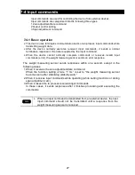
Example of setting
(When ID=5)
5–8
All set to OFF
1–4
ID setting
Summary of Contents for UD-1
Page 52: ...48 Appendix 3 Outlines Weight measuring sensor UF 620 UF 3200 ...
Page 53: ...49 Indicator ...
Page 54: ......
Page 55: ...はくし ...
Page 56: ...はくし ...


