background image

6

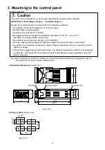
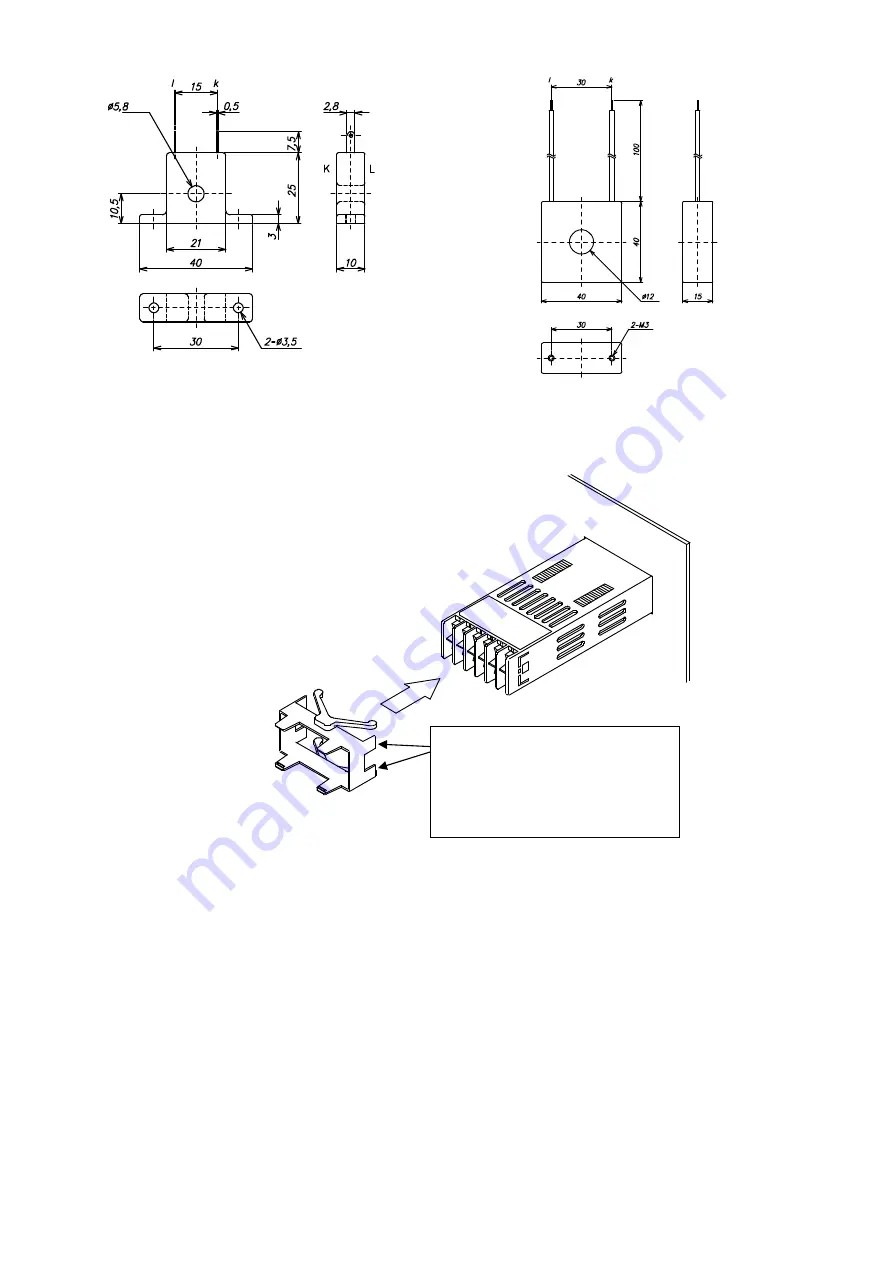
3.4 CT (Current transformer) external dimensions

(Scale: mm)

CTL-6S (for 5A, 10A, 20A)

CTL-12-S36-10L1U (for 50A)

(Fig. 3.4-1)

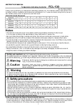
3.5 Mounting

Mountable panel thickness: 1 to 10mm.
Insert the FCL from the front of the
panel.
Insert the mounting frame as shown in
(Fig. 3.5-1) until the four tips of
the frame touch the panel.

(Fig. 3.5-1)

Insert the mounting frame until
these 4 flanges (including the 2
flanges on the opposite side)
touch the back of the control
panel.

Summary of Contents for FCL-130

Page 1: ...be linked to serious results so be sure to follow the directions for usage Warning Warning To prevent an electric shock or fire only Shinko or qualified service personnel may handle the inner assembly To prevent an electric shock fire or damage to the instrument parts replacement may only be undertaken by Shinko or other qualified service personnel Safety precautions To ensure safe and correct use...

Page 2: ...d to the screw when tightening the terminal screw or case may be damaged This instrument does not have a built in power switch circuit breaker or fuse It is necessary to install them near the controller Recommended fuse Time lag fuse rated voltage 250V AC rated current 2A For a 24V AC DC power source do not confuse polarity when using direct current DC Do not apply a commercial power source to the...

Page 3: ...R drive Control output OUT A DC current 4 to 20mA DC M Multi range input Input E TC K input C5 Serial communication RS 485 W 5A Rated current 5A W 10A Rated current 10A W 20A Rated current 20A W 50A Heater burnout alarm Rated current 50A SM Set value memory external selection TC Terminal cover Option BK Color black 0 to 400 0 0 to 400 0 0 to 750 Range user specified 0 0 to 750 0 Specify a range on...

Page 4: ... while controlled with the SV2 desired value 2 3 PV SV display Red Indicates PV process variable SV desired value MV manipulated variable and characters 4 Decimal point indicator Red Lights for the set values with a decimal point Flashes when MV manipulated variable is indicated 5 OUT indicator Green Lights when the control output OUT is ON For DC current type flashes corresponding to the manipula...

Page 5: ...large capacity electromagnetic switches or cables through which large current flows No water oil or chemicals or where the vapors of these substances can come into direct contact with the controller If the FCL is installed through the control panel the ambient temperature of the FCL must be kept to under 50 Otherwise the life of electronic parts especially electrolytic capacitors of the FCL will b...

Page 6: ...ounting Mountable panel thickness 1 to 10mm Insert the FCL from the front of the panel Insert the mounting frame as shown in Fig 3 5 1 until the four tips of the frame touch the panel Fig 3 5 1 Insert the mounting frame until these 4 flanges including the 2 flanges on the opposite side touch the back of the control panel ...

Page 7: ...rated voltage 250V AC rated current 2A For a 24V AC DC power source do not confuse polarity when using direct current DC Do not apply a commercial power source to the sensor connected to the input terminal nor allow the power source to come into contact with the sensor Use a thermocouple and compensating lead wire that correspond to the sensor input specification of this controller Use a 3 wire RT...

Page 8: ...into the hole of the CT 3 When wiring keep the CT wire away from AC sources or load wires to avoid the external interference Fig 4 3 1 5 Setup The PV SV display indicates the characters of the sensor type and temperature unit for approx 2 seconds after power on During this time all outputs and the LED indicators are in OFF status Refer to Table 5 1 and Table 5 2 Control will then start indicating ...

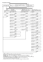
Page 9: ...ction Heater burnout alarm value Communication speed Alarm type Loop break alarm time Alarm Energized De energized Loop break alarm span Alarm hysteresis Alarm action delay timer SV rise rate SV fall rate Direct Reverse control action AT bias If the key is pressed the set value is saved and the controller proceeds to the next setting item Press the key while holding down the key Approx 3sec Press ...

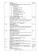
Page 10: ...e time Sets the derivative time of control output OUT Setting the value to 0 disables the function Setting range 0 to 3600 seconds 50sec Proportional cycle Sets the proportional cycle value of control output OUT Not available for ON OFF action or DC current output type Setting range 1 to 120 seconds R 30sec S 3sec Alarm value Sets the action point of the alarm output Setting the value to 0 or 0 0 ...

Page 11: ...pan to input span 199 9 to input span High Low limits alarm 0 to input span 0 0 to input span High Low limit range alarm 0 to input span 0 0 to input span Process high alarm Input range low limit to input range high limit Input range low limit to input range high limit Process low alarm Input range low limit to input range high limit Input range low limit to input range high limit High limit alarm...

Page 12: ...e memory Do not change any setting item in Auxiliary function setting mode 2 If any item in the mode is changed it will affect other setting items such as the SV and alarm value Unlock SV high limit Sets the SV high limit value Setting range SV low limit to input range high limit Multi range input TC multi range input 1370 TC K input 400 SV low limit Sets the SV low limit value Setting range Input...

Page 13: ...00 K 0 0 to 400 0 K 0 to 750 K 0 0 to 750 0 PV filter time constant Sets PV filter time constant value If the value is set too large it affects control result due to the delay of response Setting range 0 0 to 10 0 seconds 0 0sec OUT high limit Sets control output OUT high limit value Not available for the ON OFF action Setting range OUT low limit to 100 DC current output type OUT low limit to 105 ...

Page 14: ...action is selected during Alarm type selection Not available if Alarm is not selected during Event output function selection However available when the C5 option is added Setting range 0 1 to 100 0 1 0 Alarm action delay timer Sets the alarm action delay timer When setting time has elapsed after the input enters the alarm output range the alarm is activated Not available for the FCL 130 Not availa...

Page 15: ...ized is selected event output between terminals 11 and 12 is conducted ON while the event output indicator is lit Event output is not conducted OFF while the event output indicator is not lit When the alarm action De energized is selected event output between terminals 11 and 12 is not conducted OFF while the event output indicator is lit Event output is conducted ON while the event output indicat...

Page 16: ...hermocouple or RTD is burnt out or if the input value exceeds the Input range high limit value 50 100 or more the control output OUT is turned off for DC current output type OUT low limit value and flashes on the PV SV display However when the input range high limit value is 999 9 if the input value exceeds 999 9 flashes on the PV SV display and the control is performed until 999 9 1 of input span...

Page 17: ...DC 12V DC 20mA DC 20 to 4mA DC 4mA DC 4mA DC 4 to 20mA DC 20mA DC 3 4 3 3 4 4 3 4 4 4 3 3 3 4 3 4 4 4 4 4 3 3 3 3 4 3 3 3 3 3 4 4 4 4 4 3 Cycle action according to deviation Cycle action according to deviation Cycle action according to deviation Changes continuously according to deviation ON OFF ON OFF Indicator OUT Green DC current output Lit Unlit Lit Unlit part Acts ON or OFF Non contact voltag...

Page 18: ...arm action High limit alarm with standby High Low limits alarm with standby Acts ON or OFF The standby functions 11 12 12 11 11 12 11 12 11 12 11 12 11 12 12 11 11 12 12 11 12 11 11 12 11 12 11 12 11 12 12 11 12 11 11 12 11 12 11 12 11 12 ON OFF ON OFF ON OFF Alarm action Output Indicator Lit Lit Unlit Unlit Unlit Lit Unlit 12 11 11 12 11 12 12 11 11 12 12 11 12 11 Hysteresis Hysteresis Hysteresis...

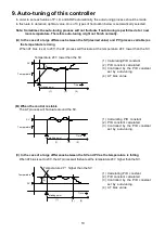
Page 19: ...SV 1 Calculating PID constant 2 PID constant calculated 3 Controlled by the PID constant set by auto tuning 4 AT bias value B When the control is stable The AT process will fluctuate around the SV 1 Calculating PID constant 2 PID constant calculated 3 Controlled by the PID constant set by auto tuning C In the case of a large difference between the SV and PV as the temperature is falling WhenAT bia...

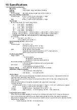
Page 20: ... resistive load 1A 250V AC inductive load cos 0 4 Non contact voltage For SSR drive 12 2 0V DC Maximum 40mA short circuit protected DC current 4 to 20mA DC Load resistance maximum 550 Supply voltage 100 to 240V AC 50 60Hz 24V AC DC 50 60Hz Allowable voltage fluctuation 100 to 240V AC 85 to 264V AC 24V AC DC 20 to 28V AC DC Alarm output When alarm action is set as Energized the alarm action point i...

Page 21: ...ween input terminal and ground 1 5kV AC for 1 minute Between input terminal and power terminal 1 5kV AC for 1 minute Between power terminal and ground 1 5kV AC for 1 minute Between output terminal and ground 1 5kV AC for 1 minute Between output terminal and power terminal 1 5kV AC for 1 minute Power consumption Approx 5VA Ambient temperature 0 to 50 32 to 122 Ambient humidity 35 to 85 RH non conde...

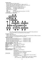
Page 22: ... to DC current output type Rated current 5A W 5A option 10A W 10A option 20A W 20A option 50A W 50A option Setting range Rated current 5A 0 0 to 5 0A off when set to 0 0 Rated current 10A 0 0 to 10 0A off when set to 0 0 Rated current 20A 0 0 to 20 0A off when set to 0 0 Rated current 50A 0 0 to 50 0A off when set to 0 0 Setting accuracy 5 Input resolution 1 200 of each rated current Action ON OFF...

Page 23: ...ire is correct Check whether codes A B B of the RTD agree with the controller terminals Ensure that they are wired properly The indication of the PV SV display is irregular or unstable Check whether the sensor input and temperature unit or setting are correct Set the sensor input and the temperature unit properly Sensor correction value is unsuitable Set it to a suitable value Sensor specification...

Page 24: ...he sensor Check whether Thermocouple or RTD lead wire is securely connected to the instrument terminals Ensure that the wiring of control output terminals is correct The control output OUT remains in an ON status OUT low limit value is set to 100 or higher in Auxiliary function setting mode 2 Set it to a suitable value The control output OUT remains in an OFF status OUT high limit value is set to ...

Reviews: