9
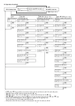
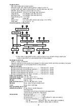
5.1 Operation flowchart
PV/SV display mode
(
Approx. 1sec)
Control output OFF function
[
]
Output MV indication
(Approx. 3sec)
+
+
(Approx. 3sec)
+
+
(Approx. 3sec)
[
Main setting mode
]
[
Sub setting mode
]
[
Auxiliary function setting mode 1
]
[
Auxiliary function setting mode 2
]
SV1
[
]
Auto-tuning/Auto-reset
[
/
]
PV/SV display switching
[
/
]
Input type
[
]
SV2
[
]
Proportional band
[
]
Set value lock
[
]
PV filter time constant
[
]
Integral time
[
]
SV high limit
[
]
OUT high limit
[
]
Derivative time
[
]
SV low limit
[
]
OUT low limit
[
]
Proportional cycle
[
]
Sensor correction
[
]
OUT ON/OFF hysteresis
[
]
Alarm value
[
]
Instrument number
[
]
Event output function
[
]
Heater burnout alarm value
[
]
Communication speed
[
]
Alarm type
[
]
Loop break alarm time
[
]
Alarm Energized/De-energized
[
]
Loop break alarm span
[
]
Alarm hysteresis
[
]
Alarm action delay timer
[
]
SV rise rate
[
]
SV fall rate
[
]
Direct/Reverse control action
[
]
AT bias
[
]
•
: If the
key is pressed, the set value is saved, and the controller proceeds to the next setting item.
•
+
: Press the
key while holding down the
key.
•
+
(Approx. 3sec): Press the
key for 3 seconds while holding down the
key.
•
+
+
(Approx. 3sec): Press the
key for 3 seconds while holding down the
and
keys.
•
To revert to the PV/SV display mode, press the
key for approx. 3sec during setting mode.
The unit will revert to the PV/SV display mode from any mode.
•
Setting items with dotted lines are optional, and they appear only when the options are added.

