background image

98

Address

Relative
address

(HEX)

Name

Arrange

ment

Description

Remarks

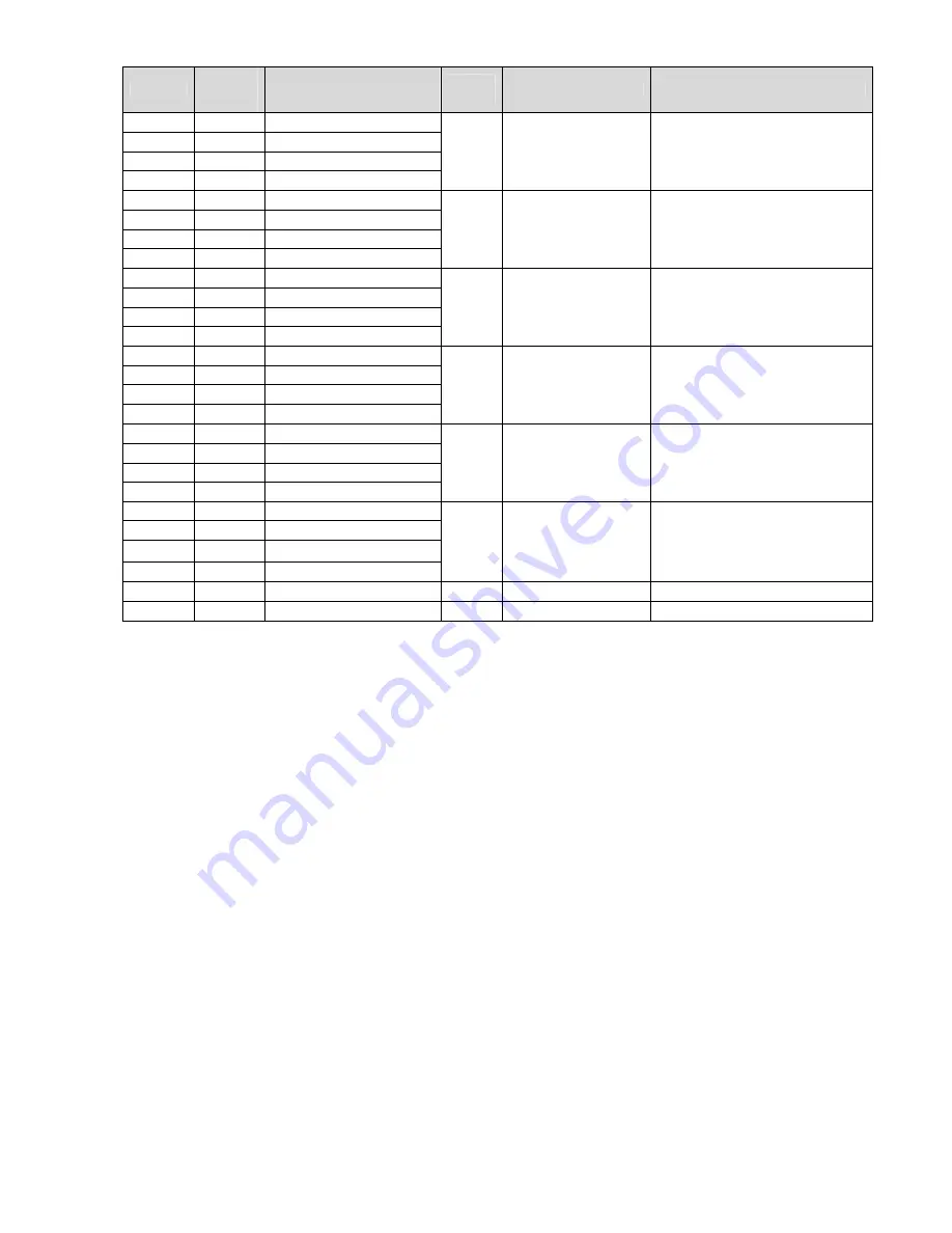
30131

82 Unit (1/4)

30132

83 Unit (2/4)

30133

84 Unit (3/4)

30134

85 Unit (4/4)

CH01

Current unit

30135

86 Unit (1/4)

30136

87 Unit (2/4)

30137

88 Unit (3/4)

30138

89 Unit (4/4)

CH02

Current unit

30139

8A Unit (1/4)

30140

8B Unit (2/4)

30141

8C Unit (3/4)

30142

8D Unit (4/4)

CH03

Current unit

30143

8E Unit (1/4)

30144

8F Unit (2/4)

30145

90 Unit (3/4)

30146

91 Unit (4/4)

CH04

Current unit

30147

92 Unit (1/4)

30148

93 Unit (2/4)

30149

94 Unit (3/4)

30150

95 Unit (4/4)

CH05

Current unit

30151

96 Unit (1/4)

30152

97 Unit (2/4)

30153

98 Unit (3/4)

30154

99 Unit (4/4)

CH06

Current unit

30155

9A Reserve

・・・

・・・

8.3.5 Reading from or Writing to the Holding Register Area

The holding register area is a read-write area. Parameter settings and the start and stop

command of the recording state are mapped. For read, specify the start address (relative) and

data count (assuming that one word is two bytes) of the data to be read. For write, specify the

start address and the data to be written.

For details, see the separate ”RM10C HYBRID RECORDER COMMUNICATION COMMAND

INSTRUCTION MANUAL (HXPRM10mnC0005E) ”.

Summary of Contents for HR-706

Page 1: ...HYBRID RECORDER HR 706 DOT PRINTING INSTRUCTION MANUAL ...

Page 2: ...tive use Be sure to observe the following warnings cautions and those written in this manual in order to ensure safety when using this instrument WARNING 1 In order to prevent electric shock be sure to disconnect this instrument from the main power source when wiring it 2 When this instrument is incorprated in a system and if the system is expected to be affected by malfunction from the recorder o...

Page 3: ... way 2 Do not incinerate plastics from the maintenance parts or replacement parts Harmful gases may be produced 1 Use a dry cloth to clean the surface of this instrument 2 Do not use any organic solvent 3 Clean the instrument after the power is turned off This instruction manual is subject to change without prior notice SAFETY PRECAUTIONS To ensure safe and correct use thoroughly read and understa...

Page 4: ... HR71E Explanation for installation wiring standard operation Setting and operation for using this instrument 2 HR 700 Hybrid Recorder Communication Command instruction manual No HR7CE Explanation for reading and writing data of the recorder by communication function Initial setting checking list After installing and wiring the HR 706 the following items are the minimum required setting items befo...

Page 5: ... Start Stop Printing 39 6 4 5 DI Manual Printing DI option 39 6 4 6 DI Date Time Printing DI option 39 6 4 7 DI Comment Printing DI option 40 6 5 Changing the Display 41 6 5 1 Auto Display 41 6 5 2 Manual Display 41 6 5 3 Date Display 41 6 5 4 Time Display 41 6 5 5 Display Off 41 7 DEVICE SETTING 42 7 1 Setting the Setup Mode 42 7 1 1 Setting the Range 45 1 Setting Method 45 2 Current Voltage Ther...

Page 6: ...ation of Voltage 101 2 Calibration of RTD Resistance temperature detector 101 3 Calibration of Reference Junction Compensation 102 10 TROUBLESHOOTING 103 10 1 Troubleshooting 103 10 1 1 Problems 103 10 1 2 When the Recorder Dose not Work at All 103 10 1 3 When There is a Large Error 104 10 1 4 When the Trend Recording is Deflected 104 10 1 5 When Nothing is Recorded 105 10 1 6 When Printing is Fai...

Page 7: ...The following accessories are included with the recorder 1 Chart paper 2 Ribbon cassette 3 Mounting brackets 4 Instruction manual 5 Packing Fig 1 1 Accessories Table 1 1 List of Accessories No Part Name Type Quantity Remarks 1 Chart paper H 10100 1 100 equal divisions 2 Ribbon Cassette WPSR188A000001A 1 3 Mounting bracket H4A14175 2 Panel mounting bracket 4 Instruction manual HR71E 1 This manual 5...

Page 8: ...he nameplate is put in the middle far side of the instrument Make sure that this instrument meets your requested specification checking the following table Table 1 2 Model type H R 7 0 6 144 W x 144 H x 150 D mm Measuring point 6 6 points C5 Communication function RS 485 RE6 DI function FL6 Paper empty detection function Options LH6 Alarm output function ...

Page 9: ...e in a poor environment may damage the appearance functions and service life of the instrument Storage Environment A place free from excess dust A place free from combustible explosive or corrosive gases SO2 H2S etc A place free from vibrations or shocks A place free from water or steam or high humidity 95 RH max A place free from direct sunlight or high temperature 50 max A place free from an ext...

Page 10: ...9 2 CONSTRUCTION 2 1 Appearance Fig 2 1 Appearance Terminal block Mounting bracket Ribbon cassette Door Chart holder Display keyboard Printer Case Location ID card ...

Page 11: ... Alphabet M N O P Q R S T U V W X Y Z Alarm Type Indicator Indicates an alarm type in red H is lit when the alarm is High And L is lit when the alarm is Low Neither of them is lit when there is no alarm Channel No Display Indicates channel number in orange Data Display Indicates the process variable time setting screen etc in orange Operation Keys Use these keys for setting and other operations St...

Page 12: ...ng and changes the mode to the setting mode ESC key ESC function While selecting a function exits that menu without finishing PRINT key PRINTING function Used to perform manual printing or list printing key function Used to select a setting parameter numeral or built in command ascending direction FEED key FEED function The chart paper is fed while the key is pressed and stopped when released key ...

Page 13: ...rackets is the minimum secure spacing Dimension required when the door is fully open 135 degrees Wall on left side Scale mm Front Rear Side Panel Cutout 137 137 128 128 7 max Pannel thickness 25 150 56 144 144 3 5 2 5 100 200 min 200 min 138 1 0 138 1 0 L N 1A 2C 2A 1C 3A 4C 4A 3C 5A 6C 6A 5C 4 B 4 B 4 A 5 B 5 B 5 A 6 B 6 B 6 A 1 B 1 B 1 A 2 B 2 B 2 A 3 B 3 B 3 A SG RD TD DI COM DI 3 DI 2 DI 1 ...

Page 14: ...nstall the instrument only in the following conditions A place without rapid humidity change A place of normal temperature around 25 A place exposed to as few mechanical vibrations as possible A place with as little dust as possible A place affected by electromagnetic fields as little as possible A place not directly exposed to high radiant heat A place of altitude below 2000 m Humidity has an eff...

Page 15: ...or to mounting the instrument to the panel attach packing to the position shown in the figure The rest of the procedure is the same Fig 3 2 2 Panel Mounting in compliance with the IP65 Mounting of Packing Packing Panel Mounting bracket Packing Panel Screw Panel Mounting bracket Screw ...

Page 16: ...ock Option RE6 WARNING 1 In order to prevent an electric shock be sure to provide protective grounding prior to supplying power to the instrument 2 Do not cut the protective grounding conductor or disconnect protective grounding 3 Make sure that the supply voltage for the instrument conforms to the voltage of the supply source 4 Attach a transparent protective cover prior to switching on power to ...

Page 17: ... there may be interference caused by noise coming from the grounding conductor Do not share the grounding conductor with other instruments 5 In order to comply with the requirements of safety standard EN61010 1 the recorder should have one of the following as a disconnecting device fitted within easy reach of the operator and labeled as the disconnecting device a A switch or circuit breaker which ...

Page 18: ...hielded input line should be used For Pt100 JPt100 50 m max When it is likely to be affected by induction noise particularly when wiring near a high frequency power source a shielded twisted wire should be used Attach a ring type solderless terminal with an insulated sleeve for M3 5 to the end of the electric wire 2 Precautions for wiring The wiring between the instrument and measurement point sho...

Page 19: ... 19 3 Attach transparent protective covers mV V inputs Thermocouple input Fig 4 2 1 2 Input Wiring mV V Thermocouple inputs CAUTION To remove the transparent protective cover release the left and right both sides hooks simultaneously If they are released one after the other the cover may be damaged 4 B 4 B 4 A 5 B 5 B 5 A 6 B 6 B 6 A DI COM DI 3 DI 2 DI 1 TD RD SG 1 B 1 B 1 A 2 B 2 B 2 A 3 B 3 B 3...

Page 20: ...B A B B A B B A Shunt resistor CAUTION 1 Attach a shunt resistor to the input terminal block of the instrument 2 A shunt resistor affects input accuracy Use the following resistor Resistance 250 Rated power 1 4 W Tolerance 0 1 max Temperature coefficient 50 ppm max ...

Page 21: ...ut contact capacity should be a withstanding voltage of 50 V DC 16 mA or more ON resistance of 20 max Wiring resistance included 3 Do not use unused terminals as relay terminals Precautions for Wiring the Alarm Output 1 An alarm output contact capacity is as follows 250 V AC 3 A max Resistive load 30 V DC 3 A max Resistive load 125 V DC 0 5 A max Resistive load 0 1 A max L R 7 ms max Inductive loa...

Page 22: ... DI Function Wiring L N 1A 1C 2A 2C 3A 3C 4A 4C 5A 5C 6A 6C 6 Relay output 1C 1A Relay No 1 Normally open 6C 6A Relay No 6 Normally open DI1 DI2 DI3 DI COM COMMON to DI1 to DI3 L N 1A 2C 2A 1C 3A 4C 4A 3C 5A 6C 6A 5C 4 B 4 B 4 A 5 B 5 B 5 A 6 B 6 B 6 A 1 B 1 B 1 A 2 B 2 B 2 A 3 B 3 B 3 A SG RD TD DI COM DI 3 DI 2 DI 1 CAUTION Relay No 1 is a common output for Alarm output and Paper empty detection...

Page 23: ...o be affected by induction noise particularly when wiring near a high frequency power source a shielded twisted wire should be used 3 Attach a ring type solderless terminal with an insulation sleeve for M3 5 to the end of the electric wire 4 Be sure to ground the shield of a connecting wire Note 1 Be sure to attach terminating resistance 200 to a host computer side and attach it to the remotest HR...

Page 24: ... used to ensure proper recording If the chart holder is taken out and the recording operation is activated the ink ribbon may be damaged To replace the chart paper be sure to press the REC key to stop recording Door Hook Push the door hook in the arrow direction to unlock Press the key for 3 seconds or longer CAUTION Maximum angle of the fully opened door is 135 degrees Do not open the door any fu...

Page 25: ...ulling out the Chart Holder 4 Open the Chart Cover and Chart Guide Open the chart guide and the chart cover outward Fig 5 1 4 Opening the Chart Cover and Chart Guide Pull out the chart holder Lever Chart Guide Transparent Chart Cover Black Open the chart guide in the arrow direction Open the chart cover in the arrow direction ...

Page 26: ...er Fig 5 1 5 Loosening the Chart Paper 6 Set the Chart Paper into the Storage Chamber Unfold 2 sections of chart paper Holding the printing surface upward set it in the storage chamber Fig 5 1 6 Setting the Chart Paper Square Holes on the Left Sprocket Drum Storage Chamber Rectangular Holes on the Right ...

Page 27: ...hart Paper with the Sprocket Drum Chart Holder Sectional View 8 Close the Chart Cover and Chart Guide Close the chart cover and the chart guide in the arrow directions Fig 5 1 8 Closing the Chart Cover and Chart Guide Ensure that the left and right holes are parallel with each other Chart Paper Chart Paper Chart Receiver Storage Chamber Align the holes in the paper properly with the sprocket drum ...

Page 28: ...chart paper should be fed out Fig 5 1 9 Checking Paper Feed 10 Put the Chart Holder back Insert the chart holder horizontally into the case until it is locked Fig 5 1 10 Putting Back the Chart Holder Turn the gear at the left end of the sprocket drum in the arrow direction Chart receiver Chart guide Push the Chart receiver for insertion ...

Page 29: ...FEED key 13 Press the REC Key to restart Operation The chart paper is fed while pressing the key Releasing the key stops paper feed The paper begins a slow feed when the key is pressed Prior to operation of the instrument be sure to confirm that the chart paper is being fed L M Caution Be careful when opening the door more than 90 degrees Also make sure that the display cable does not get caught ...

Page 30: ...on holder pull the ribbon cassette toward you Fig 5 2 1 Taking Out the Ribbon Cassette CAUTION If recording operation is activated while the chart holder is removed the ink ribbon may be damaged To replace the ribbon cassette be sure to press the REC key to stop recording If the ribbon cassette is not set properly the recording color may change or the ribbon may be damaged Ribbon Cassette Ribbon H...

Page 31: ... the gear in the direction of an arrow to adjust the position When this is done push the ribbon cassette until the latch clicks Fig 5 2 3 Setting the Ribbon Cassette 6 Close the Door 7 Press the REC key to restart Operation Turn the knob in the arrow direction Knob Slack Ribbon feeding shaft First push the right side Second push the left side until it firmly fits in the ribbon holder Caution Be ca...

Page 32: ...after power recovery when the power is turned off during printout 3 When the power is turned on the display indicates while reading data in Fig 6 1 1 The number of indicated digits differs depending on the setting CAUTION 1 This recorder has no power switch 2 Prior to switching the power on make sure that the chart paper is set in the chart holder If the printer is activated with no chart paper se...

Page 33: ...fed while the FEED key is pressed and stops when released CAUTION 1 The instrument checks zero point for every recording If the printer block is manually moved during recording the recording position may be dislocated 2 In order to protect the chart paper dot printing is not performed when the distance between the previous dot printing position and the current one for an identical channel is less ...

Page 34: ...chronous printing Performs digital printing with the same speed as the analog recording Asynchronous printing Stops analog recording and performs digital printing After digital printing is completed restarts analog printing Note Logging printing will not be in the printing queue At the start time of Logging printing if prior Logging printing is printing the next log will not print In this case pro...

Page 35: ...ffective 2 If an alarm is activated while manual printing is running alarm printing will start from the time when manual printing finished Reference Printing is activated in the following priority order When multiple types of printing are activated simultaneously higher priority printing takes effect first by following the priority order However while alarm printing is performed lower category Log...

Page 36: ...ng cycle Channel number range scaling value engineering unit Setting alarm type 1 List printing operating procedure 1 Press the PRINT key 2 Use the PRINT key to display and press the ENT key 3 Use the PRINT key to select Pressing the ENT key executes the list printing Once list printing starts the display automatically returns to the Data Display screen Upon termination of the list printing the di...

Page 37: ...3 10V 10 000V 10 000 4 10V 10 000V 10 000 5 TYPE K 200 00 100 00 6 10V 10 000V 10 000 CH ALARM1 RLY ALARM2 RLY ALARM3 RLY ALARM4 RLY UNIT 1 H 8 000 L 5 000 V CH DIGITAL ZONE mm PARTIAL 1 ON 0 100 2 OFF 0 50 80 0 000V 3 OFF 0 100 4 OFF 0 100 5 ON 50 100 6 OFF 0 100 COMMENT 1 OPEN 2 3 Digital printing ON OFF zone recording and partial compression expansion set value for each channel Prints Input ran...

Page 38: ... Pressing the ENT key executes engineering list printing Once engineering list printing starts the display automatically returns to the Data Display screen Upon termination of the engineering list printing the display returns to the status prior to starting engineering list printing Note Analog recording is interrupted while engineering list printing is running However measurement alarm detection ...

Page 39: ...OFFSET COLOR 1 OFF INT 0 0 PRP 2 OFF INT 0 0 RED 3 OFF INT 0 0 GRN 4 OFF CH 0 0 BLU 5 OFF EXT 798 0 0 BRN 6 OFF CH CH5 0 0 BLK COM_ADR SPEED DATA PARITY STOP 01 9600bps 8bit NONE 1bit DI 1 OFF 2 OFF 3 OFF Alarm Printing ON1 occurrence recovery Settings of Logging Printing ON OFF Start Time Interval Scale Printing ON OFF Printing Sync Async Logging Printing ON Start Time 00 00 Interval 6h Scale Pri...

Page 40: ...I Manual Printing DI option DI Manual printing occurs by turning the DI from OFF to ON Current measured value and time will be printed on the chart paper Printing contents are the same as Section 6 4 1 Manual Printing 1 Select Manual Printing of DI function in Engineering Mode For detailed setting method refer to Section 7 2 9 DI Functions MAN P Synchronous Manual printing AMAN P Asynchronous Manu...

Page 41: ... DI function in Engineering mode For detailed setting method refer to 7 2 9 DI Functions CMNT1 CMNT2 CMNT3 Synchronous comment printing ACMT1 ACMT2 ACMT3 Asynchronous comment printing 2 Turn the DI input ON DI Comment printing starts by turning the DI input from OFF to ON Fig 6 4 7 Date Time Printing Comment Printing May 10 06 20 30 20 10 No 01 OPEN Comment Printing Date Time Printing ...

Page 42: ...ly at intervals of 2 5 seconds 6 5 2 Manual Display Displays the process variable of the specific channel and updates it every measurement cycle The data is the same as that of Auto display Pressing the ENT key changes to the next displayed channel number 6 5 3 Date Display Displays the month and day Leap year is adjusted automatically e g October 18 6 5 4 Time Display Displays the hour and minute...

Page 43: ... 7 1 1 Setting the Range 7 1 2 Setting the Alarm Setting Channel Mode Setting Channel ON OFF Level Set value Type Relay ON OFF Relay No Option WARNING When calibrating data connect equipment according to Section 9 5 of the instruction manual Data calibration must be performed correctly Operators possessing knowledge of electricity and control related matters should perform the calibration after ca...

Page 44: ...on Digital Printing Tag Comments Shift to the engineering mode Printing Cycle Zone Recording Partial Compression Expansion Digital Printing Tag Comments Setting Mode Setting Channel to copy from Channel to copy to Setting 1st 2nd Chart speed Chart speed Time Setting Year Month Day Setting Channel Code No Char No End Setting Password Input the password to enter engineering mode See the key operatio...

Page 45: ... 43 00 Chart feed speed 1st speed 20 mm h 2nd speed 20 mm h Time 2000 01 01 00 00 The present time has been set Japan standard time GMT 09 00 Dot point interval 10 sec Zone setting all channels 0 to 100 Partial compression expansion all channels OFF Digital printing all channels ON Tag printing character all channels Blank up to the 7th character Comment printing word 1 to 3 Blank up to the 16th c...

Page 46: ... scaling square root decade interchannel sum difference average Modes 4 to 9 Unnecessary channels can be skipped Mode 10 Setting Channel Mode Key 1 Voltage Current 2 Thermocouple 3 Resistance temperature detector 4 Scaling 5 Square root 6 Decade 7 Difference 8 Sum 9 Average 10 Skip key Can be set for all channels Note A decimal point arbitrary position can be set only in scaling and square root mo...

Page 47: ...the key to shift a digit Press the ENT key Use the key to select a sign and numeral Use the key to shift a digit Press the ENT key Press the ENT key Setting is completed To return to user mode press the MENU key for 3 seconds or longer Display Operation keys Description MENU ESC 3 sec ENT PRINT ENT PRINT ENT PRINT ENT FEED PRINT ENT FEED PRINT ENT ENT Span setting Zero setting Note When an incorre...

Page 48: ...5 V 10 V 4 to 20 mA Range Mode B R S K E J T C Au Fe N PR40 20 PL U L Pt100 JPt100 Reference The following ranges input types have more than one measurement range and their accuracy is different depending on the measurement range An optimum range input type is automatically selected by the set span point Thermocouple R K E J T RTD Pt100 JPt100 ...

Page 49: ...is selected here temperature input scaling is possible Use the key to select a range 50 mV Press the ENT key Use the key to select a numeral Use the key to shift a digit Press the ENT key Use the key to select a numeral Use the key to shift a digit Press the ENT key FEED PRINT ENT Span input value Display Operation keys Description MENU ESC 3 sec ENT PRINT ENT PRINT ENT PRINT ENT PRINT ENT FEED PR...

Page 50: ...ey Use the key to select a numeral Use the key to shift a digit Press the ENT key Press the ENT key Setting is completed To return to user mode press the MENU key for 3 seconds or longer FEED PRINT ENT FEED PRINT FEED PRINT ENT ENT Decimal point Zero side scale value 1 Span side scale value 2 Note When an incorrect numeral is entered or is displayed Press the ENT key and re enter the correct numer...

Page 51: ...key to shift a digit Press the ENT key Use the key to select a numeral Use the key to shift a digit Press the key again at the lowest digit at right to flash a decimal point Use the key to select a decimal point position Press the ENT key Use the key to select a numeral Use the key to shift a digit Press the ENT key Press the ENT key Setting is completed To return to user mode press the MENU key f...

Page 52: ...nput voltage OUT Output Scaling value When an input value is 1 or more 1 to 100 OUT SCAL R SCAL L x SCAL L When an input value is less than 1 OUT x IN SPAN L SCAL L Example When setting on the previous page is performed the display is shown as below Input voltage mV 0 10 20 30 40 Display 0 00 50 00 70 71 86 63 100 00 Note The relation between scaling factor and displaying digit may stagger the acc...

Page 53: ...to shift a digit Press the ENT key Use the key to select a numeral Use the key to shift a digit Press the ENT key Use the key to select a numeral Use the key to shift a digit Press the ENT key Use the key to select a numeral Use the key to shift a digit Press the ENT key Press the ENT key Setting is completed To return to user mode press the MENU key for 3 seconds or longer MENU ESC 3 sec ENT PRIN...

Page 54: ...UT 10 OUT1 LGSCAL L Log10 SCAL L LGSCAL R Log10 SCAL R Example When setting on the previous page is performed the display is shown as below Input voltage V 0 0 1 0 2 5 3 0 5 0 Display 1 0E0 1 0E1 3 2E2 1 0E3 1 0E5 LGSCAL R LGSCAL L SPAN R SPAN L SPAN R x LGSCAL L SPAN L x LGSCAL R SPAN R SPAN L XXEYY XX Mantissa section 1 0 to 9 9 YY Exponent section 19 to 19 Up to 5 decades Scaling upper limit Sc...

Page 55: ... press the MENU key for 3 seconds or longer About Difference Sum and Average The channel to be set must be larger than the one which computes the difference sum or average value e g When setting to Ch6 a value from Ch1 to Ch5 can be subtracted from Ch6 The range and scale of the channel to be set is the same as those of the reference channel which computes the difference sum or average value The r...

Page 56: ...ing is completed To return to user mode press the MENU key for 3 seconds or longer Note If all channels are set to Skip is displayed At least one channel should be set to Measurement Measurement can be conducted on a skipped channel however display printing or alarm assessment cannot be performed If input is not connected be sure to short circuit the input terminal To return the skipped settings t...

Page 57: ...or 3 seconds or longer to enter the setup mode Use the key to display Press the ENT key Use the key to select the desired channel Press the ENT key Use the key to select an alarm level Press the ENT key Up to 4 levels can be set Use the key to select alarm setting ON Press the ENT key Setting to displays and completes setting Use the key to select an alarm type Press the ENT key Set an alarm point...

Page 58: ... press the ENT key If the alarm output is not used select OFF and press the ENT key If the alarm output is set to ON set the relay number Use the key to select a relay number 1 to 6 and press the ENT key Press the ENT key Setting is completed To continue to set other channels press the key to select a channel and start setting To return to user mode press the MENU key for 3 seconds or longer Note ...

Page 59: ...e manner When the number of unit characters is less than 6 enter the code to finish Press the ENT key Press the ENT key Setting is completed To return to user mode press the MENU key for 3 seconds or longer Note To change the unit in the range of or set the range to Note The unit setting is effective only when the range setting is and For the and the unit setting is effective only when reference c...

Page 60: ...2 2 B R b r 2 2 B Σ β σ 3 3 C S c s 3 3 Γ T γ τ 4 4 D T d t 4 4 Y δ υ 5 5 E U e u 5 5 E Φ ε φ 6 6 F V f v 6 6 Z X ζ χ 7 7 G W g w 7 7 H Ψ η ψ 8 8 H X h x 8 8 Θ θ ω 9 9 I Y i y 9 9 I ι A J Z j z K κ B K k Λ λ C L l M μ D M m N ν E N n Ξ ξ F O o o o Ο o Setting example The code number for C is 43 ...

Page 61: ...play and press the ENT key Use the key to select the 1st chart feed speed and press the ENT key Use the key to set the 1st chart feed speed and press the ENT key Press the ENT key To return to user mode press the MENU key for 3 seconds or longer Note When changing the chart feed speed using the DI function option RE6 set the 2nd chart feed speed If the DI function option RE6 is not ordered setting...

Page 62: ...forcible chart feed When the chart feed speed is higher than 120 mm h the table shown above is not printed List Printing Engineering List Printing Manual Printing key DI Comment printing Asynchronous DI Date and Time printing Asynchronous DI Manual printing Asynchronous and Logging printing Asynchronous are printed regardless of the chart feed speed Printing type Chart speed mm h Alarm occurrence ...

Page 63: ...el 1 to Channel 2 Press the MENU key for 3 seconds or longer to enter setup mode Use the key to display and press the ENT key Use the key to select the channel to copy from and press the ENT key Use the key to select the channel to copy to and press the ENT key Press the ENT key To return to user mode press the MENU key for 3 seconds or longer MENU ESC 3 sec PRINT ENT ENT PRINT ENT PRINT ENT Displ...

Page 64: ...r OFF whether the measured data for each channel is printed or not 5 Tag Sets the tag which is to be printed instead of a channel number for logging printing or manual printing For tag setting up to 7 characters can be used select from Character code table on page 59 for each channel 6 Comments Sets the comments to be printed by DI function Option RE6 There are 3 kinds of comments and settings of ...

Page 65: ... the key to display and press the ENT key Use the key to select the desired channel and press the ENT key Set a zero point printing position in percentage Use the key to select a numeral and use the key to shift a digit Press the ENT key Set the span point printing position in percentage Use the same process as the zero point printing position setting Press the ENT key Setting is completed To retu...

Page 66: ...y point position in percentage Use the key to select a numeral and use the key to shift a digit Press the ENT key Set a boundary point position to 0500 0 Use the key to select a numeral and use the key to shift a digit Press the ENT key Press the ENT key Setting is completed To return to user mode press the MENU key for 3 seconds or longer Note If an incorrect numeral is entered is displayed Press...

Page 67: ...e key to select the desired channel and press the ENT key Use the key to switch from to and press the ENT key Press the ENT key Setting is completed To return to user mode press the MENU key for 3 seconds or longer Repeat the setting for other channels Note When the channel for which skip is selected during the range setting is set to ON is printed ENT MENU ESC 3 sec PRINT ENT PRINT ENT PRINT ENT ...

Page 68: ...racters in the same manner Set as the 5th character and press the ENT key Press the ENT key Setting is completed To return to user mode press the MENU key for 3 seconds or longer Note When the number of tag characters is less than 7 add code next to the last character See page 59 for Character code table MENU ESC 3 sec PRINT ENT PRINT ENT PRINT ENT ENT FEED PRINT ENT FEED PRINT ENT FEED PRINT ENT ...

Page 69: ...t character Repeat the settings up to the 16th Characters Press the ENT key Setting is completed To return to user mode press the MENU key for 3 seconds or longer Note When the number of tag characters is less than 16 add code next to the last character See page 59 for Character code table When DI option RE6 is not ordered comment printing does not function Do not set the comment setting ENT MENU ...

Page 70: ...on Compensation Setting ON OFF Sets the hysteresis width Cancels the hysteresis width Setting Channel ON OFF Sets burnout Cancels burnout Internal Compensation External Compensation External Channel Input Compensation Setting Channel Function Enters an offset value Setting Channel OFFSET WARNING When calibrating data connect the equipment as written in Section 9 5 of the instruction manual Data ca...

Page 71: ...printing selection Alarm printing ON OFF Logging printing ON OFF Scale printing ON OFF Recording Start Stop printing OFF Synchronous Asynchronous Setting Centigrade Unit Fahrenheit Unit Temp Unit No function RUN STOP trigger Chart feed speed selection Comment 1 printing Synchronous Comment 2 printing Synchronous Comment 3 printing Synchronous Manual printing Synchronous Date and time printing Sync...

Page 72: ...t Stop printing INT Ch OFF ON 6H 00 00 OFF Sync Synchronous OFF Use the REC key COM communication Address Communication speed Data length Parity bit Stop bit 01 9600 8 bits None 1 bit DI function Ch1 to Ch3 OFF Temperature unit centigrade unit Setting Zero point calibration Span point calibration Hysteresis at left right move Factory adjustment item Ribbon select calibration Factory adjustment ite...

Page 73: ...to display and press the ENT key Use the key to select and press the ENT key 7 2 3 Channel Offset For channel offset setting set the value to be added to an actual process variable Input value can be set from 19999 to 99999 Example Adding the value 3 0 to Channel 3 Enter engineering mode See the key operation on page 69 Use the key to display and press the ENT key Use the key to select and press t...

Page 74: ...91 V Thermocouple T input external compensator s compensating temperature 10 Electromotive force input 391 V Enter engineering mode See the key operation on page 69 Use the key to display and press the ENT key Use the key to select and press the ENT key Use the key to select and press the ENT key Use the key to alter a numerical value and the key to shift a digit Once the numerical value is determ...

Page 75: ...Trigger setting Recording RUN STOP Trigger can be set by the REC key or by the DI Example Setting Recording RUN STOP Trigger by the DI Enter engineering mode See the key operation on page 69 Use the key to display and press the ENT key Use the key to select and press the ENT key Use the key to display and press the ENT key Once setting is completed the recorder will return to Recording RUN STOP Se...

Page 76: ... screen 3 Alarm printing ON OFF Sets the alarm printing ON OFF ON1 Prints the alarm occurring and alarm recovering ON2 Prints only the alarm occurring Example When setting both alarm occurring and alarm recovering printings Enter engineering mode See the key operation on page 69 Use the key to display and press the ENT key Use the key to select and press the ENT key Use the key to display and pres...

Page 77: ...ay and press the ENT key Use the key to select and press the ENT key Use the key to display and press the ENT key Use the key to alter a numeral and key to shift a digit Then set the time and press the ENT key Use the key to display and press the ENT key Select from 10 min 15 min 20 min 30 min 1H 2H 3H 4H 6H 8H 12H and 24H Select with the key and press the ENT key Synchronous Asynchronous Once set...

Page 78: ...cording Start Stop Printing Setting screen Selection item Recording Start Stop OFF Recording Start Stop is not printed Recording Start Stop Synchronous printing Recording Start is printed at preset chart speed However Recording Stop can be printed regardless of the preset Chart feed speed Recording Start Stop Asynchronous printing Recording Start Stop is printed regardless of the preset Chart feed...

Page 79: ... Select 1 bit or 2 bits Once setting is completed the recorder will return to Communication Function Setting screen 7 2 8 Initializing the Setup Data and Calibration Data If is selected all setup mode data will revert to the default value If is selected calibration data will revert to the default value Since this function initializes all setup data and calibration data take care when executing thi...

Page 80: ...cording will not be performed Printing starts upon closing the DI terminals and the COM terminal ON 3 RUN STOP trigger RCD Recording RUN STOP can be operated externally by DI terminals Recording starts upon closing the DI terminals and the COM terminal ON Recording stops upon opening the DI terminals and the COM terminal OFF 4 Date Time printing Sync TIM P Current date and time are printed on the ...

Page 81: ... feed speed During printing measured value recording will not be performed Printing starts upon closing the DI terminals and the COM terminal ON It is possible to print up to 16 characters for Dot printing type and up to 12 characters for Pen writing type Notes when operating Recording RUN STOP When operating Recording RUN STOP externally using the DI function select 3 RUN STOP trigger RCD of the ...

Page 82: ...g mode See the key operation on page 69 Use the key to display and press the ENT key Use the key to select and press the ENT key The instrument starts to feed and print the chart paper With the move left and move right adjust the 0 mm position of the chart paper and the recording position Press the ENT key Display indicates the preset counter value Once setting is completed the recorder will retur...

Page 83: ...The instrument starts to feed and print the chart paper With the move left and move right adjust the 100 mm position of the chart paper and the recording position Press the ENT key Display indicates the preset counter value Once setting is completed the recorder will return to the Span Point Calibration screen Display Operation keys Description ENT PRINT ENT PRINT ENT PRINT ENT FEED ...

Page 84: ...dicator is unlit and press the ENT key Enter 35 mV After 10 seconds make sure that the ALM indicator is unlit and press the ENT key Enter 55 mV After 10 seconds make sure that the ALM indicator is unlit and press the ENT key Enter 200 mV After 10 seconds make sure that the ALM indicator is unlit and press the ENT key Enter 1 V After 10 seconds make sure that the ALM indicator is unlit and press th...

Page 85: ...t the other input terminals except the calibrating channel RTD calibration is required for every channel Note During calibration the ALM indicator shows the following conditions 1 When the ALM indicator is unlit 2 When the ALM indicator is flashing The calibration is within the range The recorder is assessing the input value 3 When the ALM indicator is lit The calibration is out of the range Make ...

Page 86: ...the key Then press the ENT key 7 3 Terminating the Engineering Mode Example The following describes how to save the setting data Use the key to display and press the ENT key Use the key to select and press the ENT key The settings of the engineering mode have been saved Recording starts under the new settings Note For terminal temperature calibration select a channel from Ch1 to Ch3 and select ano...

Page 87: ...n 8 1 2 Transmission Specifications 1 Communication method Half duplex communications 2 Synchronization method Start stop synchronization 3 Connection One to one RS 232C One to N RS 485 N 1 to 32 4 Protocol Original protocol Modbus RTU 5 Communication speed 1200 2400 4800 9600 19200 38400 bps 6 Start bit 1 bit 7 Stop bit 1 2 bits 8 Parity Even Odd or None 9 Data length 7 8 bits Modbus RTU 8 bits f...

Page 88: ... function all recorders which have received the command will send data As a result normal data cannot be received 1 Open Command ESC O 01 CR LF Address 01 to 32 Space 20 Hex To communicate with the recorder the host computer must issue this command and must memorize that it has issued this command 2 Close Command ESC C 01 CR LF Address 01 to 32 Space 20 Hex When sending data to the recorder to whi...

Page 89: ...e to the transmission buffer 3 Specifying the Process Variable Output Order At BINARY Mode Output BO0 CR LF Outputs start from the upper byte BO1 CR LF Outputs start from the lower byte The recorder outputs from the lower byte unless otherwise specified 4 Outputting the Data FM0 S CH E CH CR LF Specifies the ASCII mode output FM1 S CH E CH CR LF Specifies the BINARY mode output S CH Output start c...

Page 90: ...ion data S Skip All data Space 2 DS2 Data information 2 1 byte E Final data _ Space Other data 3 ALM 1 to 4 Alarm information 1 byte each 4 bytes in total H Upper limit alarm L Lower limit alarm _ Space Alarm OFF or alarm setting OFF 4 UNIT 1 to 6 UNIT 6 bytes Returns the setting unit with codes When sending the 7 bit data 1 bit information is omitted 5 CH No Channel number 2 bytes 01 to 06 6 DATA...

Page 91: ...e alarm level x LEVELxL Lower limit alarm bit at the alarm level x DATA1 DATA2 2 bytes Process variable 32000 to 32000 2 byte hexadecimal data The higher and lower bytes can be reversed by the BO command If Skip is specified 8080H will be outputted 0 0 1 0 0 0 0 1 0 0 0 1 0 0 1 0 Output bytes Date and time Process variable 1 Process variable 6 CH No A2 A4 A1 A3 DATA1 DATA2 Note Output data over 32...

Page 92: ...g channel 01 to 06 e g LF 01 06 CR LF Unit and decimal point place data output for Ch1 to Ch6 When the number of channels is 1 specify S_CH E_CH 4 Data Format DS1 DS2 CHNo UNIT1 to 6 DP CR LF 1 DS1 Data information 1 1 byte N Normal D Difference computation data S Sum computation data M Average computation data R Square root computation data C Decade computation data S Skip All data Space 2 DS2 Da...

Page 93: ... Status Output XX 00 to 19 Table 8 2 5 Status output list Status factor Status factor Status output A D END Syntax error Chart paper empty ER 00 CRLF ER 01 CRLF O ER 02 CRLF O ER 03 CRLF O O ER 04 CRLF ER 05 CRLF O ER 16 CRLF O ER 17 CRLF O O ER 18 CRLF O O ER 19 CRLF O O O O Factor by which the status is ENABLED A D END This occurs when AD conversion is completed Syntax error This occurs during a...

Page 94: ... BINARY Mode only Close Command Opens the Link Prepares for the Process Variable Output Prepares the updated data Sends the updated data Determines the Process Variable Output Order Closes the link Send once to the recorder Then it is not necessary to send it any more Send to the recorder each time Send the command when sending to another recorder Send the command to the recorder from which data t...

Page 95: ...unction code if an error occurs during command transmission an error response is returned in the fixed format described in this section Example of slave response function code 06H command error 10H Component Data length Data Slave address only for Modbus RTU 1 Function code 80H 1 86H Error code 1 10H Error check only for Modbus RTU 2 CRC Total number of bytes 5 Error codes and their occurrence con...

Page 96: ...ent Data length Data Slave address 1 Function code 1 04H Relative start address high order 1 00H Relative start address low order 1 32H Read data count high order 1 00H Data Read data count low order 1 02H Error check 2 CRC 16 bits Total number of bytes 8 Example of slave response with a start address of 0032H and a data count of 2 Component Data length Data Slave address 1 Function code 1 04H Num...

Page 97: ...E Software version 7 16 7 30016 F Software version 8 16 8 30017 10 Software version 9 16 9 30018 11 Software version 10 16 10 30019 12 Software version 11 16 11 30020 13 Software version 12 16 12 30021 14 Software version 13 16 13 30022 15 Software version 14 16 14 30023 16 Software version 15 16 15 30024 17 Software version 16 16 16 30025 18 Modbus map version 1 Binary 30026 19 Reserve 1 30027 1A...

Page 98: ...Print stops 1 During printing 30062 3D Reserve 30100 63 Reserve 30101 64 CH01 30102 65 CH02 30103 66 CH03 30104 67 CH04 30105 68 CH05 30106 69 Channel status CH06 00bit Alarm 1 1 ON 0 OFF 01bit Alarm 2 1 ON 0 OFF 02bit Alarm 3 1 ON 0 OFF 03bit Alarm 4 1 ON 0 OFF 30107 6A CH01 30108 6B CH02 30109 6C CH03 30110 6D CH04 30111 6E CH05 30112 6F Measurement data BIN CH06 32000 to 32000 Data of more than...

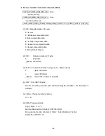
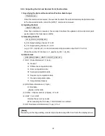
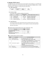
Page 99: ...8 93 Unit 2 4 30149 94 Unit 3 4 30150 95 Unit 4 4 CH05 Current unit 30151 96 Unit 1 4 30152 97 Unit 2 4 30153 98 Unit 3 4 30154 99 Unit 4 4 CH06 Current unit 30155 9A Reserve 8 3 5 Reading from or Writing to the Holding Register Area The holding register area is a read write area Parameter settings and the start and stop command of the recording state are mapped For read specify the start address ...

Page 100: ...her there are any large errors in indicated values or the dot printing position Check whether there is improper dot printing Check whether there are any blurred dot printings or printouts Check whether printout is correct Check whether the chart paper has been fed properly Check whether the chart paper is folded properly Check whether the feed holes in the chart paper are torn off or broken Check ...

Page 101: ...as it is and adjust it according to the instructions in Section 7 2 11 Point Calibration p 81 82 9 5 Calibration Data Calibration Calibrate a process variable input every year in order to keep measurement accurate Devices required for calibration Precision voltage current generator Jointly use a digital voltmeter with accuracy of 0 02 or less as required Precision dial resistor Note 1 Over time ri...

Page 102: ...rding to the instructions in Section 7 2 12 Data Calibration Calibration of the RTD See pages 83 85 Note The dispersion of resistance for each wire must be 6 m or less Calibrate RTD at every channel Short circuit the input terminals except the calibrating channel Note 1 Calibrate at any one channel 2 When a shunt resistor is attached to the input terminal block for the current input detach it prio...

Page 103: ...value then set as a correct RJC temperature 24 5 0 5 25 0 Calibrate RJC according to the instructions in Section 7 2 12 Data Calibration Calibration of reference junction compensation See Section 7 2 12 Data Calibration on p 83 Freezing Point Cold Junction Compensator Iced Water Precision Voltage Current Generator HR 706 Recorder Input Terminals Digital Voltmeter Be sure to attach terminal covers ...

Page 104: ...e feed rate Flowchart 2 p 104 Flowchart 3 p 104 Flowchart 4 p 105 Flowchart 5 p 105 Flowchart 6 p 106 Flowchart 7 p 106 Contact our dealer where you purchased the instrument or our sales representative Solution Flowchart 1 Does not work at all Power terminal connected properly Power supplied properly Power turned on Turn on the power Connect properly See section 4 1 on p 15 Supply the power proper...

Page 105: ...ion 4 2 on pages 17 19 Set them correctly See Section 7 1 1 on p 45 Contact our dealer where you purchased the instrument or our sales representative Flowchart 2 Large error Scaling setting correct Calibration correct Calibrate again See 9 5 on p 100 Set it properly See 7 1 1 on p 48 Zero span position of chart paper correct NO YES YES YES YES NO NO NO Calibrate again See 7 2 11 on pages 81 82 Dot...

Page 106: ...ly See 5 2 on Page 29 Ribbon fed properly YES NO YES NO Replace the ribbon cassette See 5 2 on Page 29 See 6 4 on Page 34 to 38 YES REC indicator is lit Digital printing enabled Contact our dealer where you purchased the instrument or our sales representative Flowchart 5 Faint printing Ribbon ink shortage YES NO Ribbon fed properly NO YES Replace the ribbon cassette See 5 2 on Page 29 Contact our ...

Page 107: ...DI contact See section 7 2 9 on p 79 YES NO NO Contact our dealer where you purchased the instrument or our sales representative Flowchart 7 Improper chart paper feed Chart cover locked properly Chart paper set properly Chart guide attached properly Attach properly See 5 1 on p 23 NO NO NO YES YES YES Lock properly See 5 1 on p 23 Used in adequate environment Set properly See 5 1 on p 23 NO Secure...

Page 108: ...sensing element of RJC Please contact our main office or dealers Calibration error Input range error at the time of voltage calibration Calibration error Input range error at the time of RTD calibration Calibrate correctly by Checking the input wiring Area error Input value is outside of the setting range Time error Clock time setting error Setting range error Setting the channel Ch1 to which sum ...

Page 109: ...ple errors occur their serial error numbers are automatically displayed When an error is recovered the error display can be canceled by pressing the REC key CAUTION While an error is indicated Auto Manual and Data Time are not indicated ...

Page 110: ...ce resistance 10 k max in mV TC input without burnout 100 max in mV TC input with burnout 1 k max in Voltage input 10 max per line in RTD input Normal mode rejection ratio 60 dB min 50 60 0 1 Hz Common mode rejection ratio 140 dB min 50 60 0 1 Hz Insulation resistance 0 5 kV DC 20 M min between each terminal and grounding terminal Withstand Voltage 1 5 kV AC for 1 minute between power terminal and...

Page 111: ...ower consumption 6 dot recorder About 25 VA About 30 VA 11 1 5 Normal Operating Conditions Ambient temperature 0 to 50 Ambient humidity 20 to 80 RH Supply voltage 85 to 264 V AC Supply frequency 45 to 65 Hz Vibration 10 to 60 Hz 0 2 m s2 max Shock Unacceptable Magnetic field 400 A m max DC and AC 50 60 Hz Noise Normal mode 50 60 Hz DC voltage Thermocouple Peak value is lower than the span width of...

Page 112: ...me as Digital indication accuracy 11 1 7 Low Voltage Directive and EMC Directive Low Voltage Directive EN61010 1 EMC Directive EN61326 1 Class A At the EN61000 4 3 test condition DC voltage DC contact range Accuracy Ratings 3 digits Thermocouple range Accuracy Ratings 5 digits Resistance temperature detector range Accuracy Ratings 10 digits 11 1 8 DI Function Option RE6 A maximum of 3 points can b...

Page 113: ...2 1 Digital Indication Accuracy Rating Measurement Indication Digital Recording Analog Type Range Measurement range Accuracy Max resolution Accuracy 10 to 10 mV 0 2 of rdg 3 digits 10 V 0 to 20 mV 0 2 of rdg 3 digits 10 V 0 to 50 mV 0 2 of rdg 2 digits 10 V 200 to 200 mV 0 2 of rdg 3 digits 100 V 1 to 1 V 0 1 of rdg 3 digits 1 mV 0 to 5 V 0 2 of rdg 2 digits 1 mV 10 to 10 V 0 3 of rdg 3 digits 10 ...

Page 114: ...er 328 to 148 0 15 of rdg 1 8 200 0 to 300 0 0 15 of rdg 0 3 However 200 to 100 0 15 of rdg 1 K3 328 0 to 572 0 0 15 of rdg 0 5 However 328 to 148 0 15 of rdg 1 8 200 0 to 800 0 0 15 of rdg 0 5 E1 328 0 to 1472 0 0 15 of rdg 0 9 200 0 to 300 0 0 15 of rdg 0 4 E2 328 0 to 572 0 0 15 of rdg 0 7 200 0 to 150 0 0 15 of rdg 0 3 E3 328 0 to 302 0 0 15 of rdg 0 5 200 0 to 1100 0 0 15 of rdg 0 5 However 2...

Page 115: ...0 15 of rdg 1 3 200 0 to 400 0 0 15 of rdg 0 5 However 200 to 100 0 15 of rdg 0 7 U 328 0 to 752 0 0 15 of rdg 0 9 However 328 to 148 0 15 of rdg 1 3 200 0 to 900 0 0 15 of rdg 0 5 However 200 to 100 0 15 of rdg 0 7 Thermocouple L 328 0 to 1652 0 0 15 of rdg 0 9 However 328 to 148 0 15 of rdg 1 3 200 0 to 650 0 0 15 of rdg 0 3 Pt100 1 328 0 to 1202 0 0 15 of rdg 0 6 200 0 to 200 0 0 15 of rdg 0 2 ...

Page 116: ...alog recording accuracy 4 1000 1000 x 10 digits 0 01 V Example 2 When Type K is 0 0 to 200 0 and Scaling is 0 00 to 200 00 Range accuracy rating 0 15 x 200 0 0 3 Input 200 0 6 6 digits Scaling factor 10 Therefore Scaling accuracy 6 x 10 2 62 digits 0 62 2 Square Root Computation The square root computation is shown as the following formula Display value 10 Process variable Display value accuracy r...

Page 117: ... x 0 003 3 6 digits Difference accuracy rating 6 x 2 12 digits 11 2 3 Individual Specifications Table 11 2 3 Individual Specification Items Block Item Specification Measuring Point 6 Input Sampling 10 sec 6CH Input Display Interval 2 5 sec Recording Form Printing Form Wire dot 6 color ink ribbon Recording Width 100 mm Printing Period 10 sec 6CH Note 1 Chart paper Length 16 m Width 114 mm Folding w...

Page 118: ...ging printing Sync Async Alarm hysteresis Burnout DI function Option Affix printing Prints Channel number near the analog record Manual printing Prints Measurement result by key input Analog recording pauses Dot printing skip Skips recording of an unused channel Programming Programs Chart feed speed Alarm setting value Logging printing interval Dot point skip Date and Time by key operation Memory ...

Page 119: ... digits are effective for indication and printing Alarm Printing Prints Occurrence time Occurrence channel Alarm setting No and Alarm type in red when an alarm occurs Alarm Recovery Printing Prints Recovery time Recovery channel Setting No and Alarm type in purple when alarm recovers Recording Start Stop Printing Prints Time and Start End comment when recording starts and stops Synchronous Asynchr...

Page 120: ...E11 2016 02 SHINKO TECHNOS CO LTD OVERSEAS DIVISION Head Office URL E mail 2 5 1 Senbahigashi Minoo Osaka Japan http www shinko technos co jp overseas shinko technos co jp Tel Fax 81 72 727 6100 81 72 727 7006 ...

Reviews: