background image

46 

11. Control action explanation 

11.1 P, I, D and ARW 

(1) Proportional band (P) 

Proportional action is the action which the control output varies in proportion to the 
deviation between the setting value and the processing temperature. 
If the proportional band is narrowed, even if the output changes by a slight variation 
of the processing temperature, better control results can be obtained as the offset 
decreases. 
However, if the proportional band is narrowed too much, even slight disturbances 
may cause variation in the processing temperature, control action changes to 
ON/OFF action and the so-called hunting phenomenon occurs. 
Therefore, when the processing temperature comes to the balanced position near 
the setting value and a constant temperature is maintained, the most suitable value 
is selected by gradually narrowing the proportional band while observing the control 
results. 
 

(2) Integral time (I) 

Integral action is used to eliminate offset. When the integral time is shortened, the 
returning speed to the setting point is accelerated. However, the cycle of oscillation 
is also accelerated and the control becomes unstable. 
 

(3) Derivative time (D) 

Derivative action is used to restore the change in the processing temperature 
according to the rate of change. It reduces the amplitude of overshoot and undershoot 
width. 
If the derivative time is shortened, restoring value becomes small, and if the derivative 
time is extended, an excessive returning phenomenon may occur and the control 
system may oscillate. 
 

(4) Anti-reset windup (ARW) 

ARW (Anti-reset windup) prevents overshoot caused by the integral action. The smaller 
the ARW value, the less the overshoot caused by the integral action in the transition 
status, however it takes time until stabilization.


When setting ARW manually, set it to the closest MV (manipulated variable) when the 
control is stabilized. 
If MV is not determined, perform trial run at default value (50%) 
 

P, I, D and ARW values are automatically set if auto-tuning is performed. 


Summary of Contents for NCL-13A

Page 1: ...MULTI DROP COMMUNICATION TYPE TEMPERATURE CONTROL UNIT NCL 13A INSTRUCTION MANUAL ...

Page 2: ...rning To prevent an electric shock or fire only Shinko or qualified service personnel may handle the inner assembly To prevent an electric shock fire or damage to instrument parts replacement may only be undertaken by Shinko or qualified service personnel SAFETY PRECAUTIONS To ensure safe and correct use thoroughly read and understand this manual before using this instrument This instrument is int...

Page 3: ...tion sleeve applicable to the connecting plugs A screw type plug for lines sold separately is required for wiring of power and communication lines Use the ferrules with an insulation sleeve in which an M2 screw fits Tighten the terminal screw within the specified torque If excessive force is applied to the screw when tightening the screw or case may be damaged Do not apply a commercial power sourc...

Page 4: ...ch it with a hard object CONTENTS 1 System configuration 6 2 Model name 2 1 Model name 7 2 2 How to read the model name label 7 3 Name and functions of the sections 8 4 Communication parameter setting 4 1 Instrument number setting 9 4 2 Communication speed and protocol selection 10 4 2 1 Communication speed selection 10 4 2 2 Communication protocol selection 10 5 Mounting 5 1 Site selection 11 5 2...

Page 5: ... D and ARW 46 11 2 Control output OUT1 action 47 11 3 Control output OUT1 ON OFF action 48 11 4 Heating Cooling control action DC option 49 11 5 Alarm 1 Alarm 2 Alarm 3 and Alarm 4 actions 52 11 6 Heater burnout alarm Actuator short circuit alarm W W3 option 53 12 Attached functions 12 1 Self diagnosis 54 12 2 Automatic cold junction temperature compensation 54 12 3 Burnout 54 12 4 Output status s...

Page 6: ...nication converter IF 400 sold separately is available using both Shinko protocol and Modbus protocol About sample program A sample program for Shinko protocol can be provided Please consult us Communication converter IF 400 RS 232C RS 485 A maximum of 31 units of the NCL 13A Power 24V DC Bus plug From each NCL 13A Host computer Screw type plug for lines sold separately Model Terminal block ATB 00...

Page 7: ...available By reading status flags in serial communication their alarm status can be assessed 2 Thermocouple RTD DC current or DC voltage can be selected from the host computer through communication function For DC current input 50 shunt resistor RES S03 050 sold separately must be installed between input terminals 2 2 How to read the model name label Warning Turn the power supply to the instrument...

Page 8: ...1 is on For DC current output a green LED flashes corresponding to the MV manipulated variable 4 Rotary switch for instrument number setting Sets the instrument number of the NCL 13A 5 Spring type plug Plug for input control output OUT1 and event output 6 CT1 CT2 input connector Connector for CT input of Heater burnout Actuator short circuit alarm W W3 option 7 DIP switch for selecting communicati...

Page 9: ...to Electric Shock Caution When the power to the unit is turned on this unit reads the contents set by the rotary switch and DIP switch If any setting is changed after the power on turn the power off and on again 4 1 Instrument number setting When communicating by connecting multiple NCL 13A units set the instrument number of each unit by means of the rotary switch Default value 0 x10 0 x 1 of Fig ...

Page 10: ...efault value 9600bps Table 4 2 1 1 DIP switch No 1 2 Communication speed OFF OFF 9600bps ON OFF 4800bps OFF ON 19200bps 4 2 2 Communication protocol selection Select the communication protocol with DIP switch 3 and 4 Default value Shinko protocol Table 4 2 2 1 DIP switch No 3 4 Communication protocol Start bit Data length Stop bit Parity bit OFF OFF Shinko protocol 1 7 1 Yes Even ON OFF Modbus ASC...

Page 11: ...f corrosive gases No flammable explosive gases No mechanical vibrations or shocks No exposure to direct sunlight an ambient temperature of 0 to 50 32 to 122 that does not change rapidly An ambient non condensing humidity of 35 to 85 RH No large capacity electromagnetic switches or cables through which large current flows No water oil or chemicals or where the vapors of these substances can come in...

Page 12: ... DIN rail is mounted in a position susceptible to vibration or shock be sure to use End plates AEP 001 1 sold separately at both ends of the unit Do not confuse the top and bottom of this unit When mounting to or removing the unit from the DIN rail the units must be slanted a little Therefore do not mount any other instruments within 50mm of space at the left side upside and down side from the uni...

Page 13: ...s plug to the DIN rail Hook the top and bottom claws of the bus plug and fit them in the DIN rail with click sound When mounting plural units link the bus plugs as shown in Fig 5 3 4 Fig 5 3 4 3 Pull the lock lever of the unit down 1 hook the unit to the DIN rail at an angle of approx 20 degrees upward 2 and mount it 3 Fig 5 3 5 Bus plug ...

Page 14: ...n the DIN rail 5 Mount the screw type plug for lines Model Terminal block ATB 001 1 sold separately to the bus plug The screw type plug Model Terminal block ATB 001 1 sold separately can also be mounted to the bus plug after wiring the power and communication lines Fig 5 3 7 Screw type plug for lines Model Terminal block ATB 001 1 sold separately ...

Page 15: ...le bus plugs are mounted separate the linking sections first By inserting the flat blade screwdriver into the slit push the plug aside using leverage Fig 5 4 2 Fig 5 4 3 1 Remove the bus plug from the DIN rail by lifting the upper claw of the plug a little Fig 5 4 3 2 Fig 5 4 2 Fig 5 4 3 Notice When separating bus plugs at the linking part do not use excessive force 1 2 Bus plug DIN rail 1 2 ...

Page 16: ...rcial power source to the sensor connected to the NCL 13A nor allow the power source to come into contact with the sensor as the input circuit may be burnt out Use a thermocouple compensating lead wire and RTD 3 wire in accordance with the input of this unit With the relay contact output type externally use a relay according to the capacity of the load to protect the built in relay contact Keep th...

Page 17: ...commended ferrules When using ferrules use the following recommended ferrules with an insulation sleeve and crimping pliers made by Phoenix Contact GMBH CO Table 6 2 1 Table 6 2 2 Table 6 2 1 Spring type plug input control output OUT1 event output terminals terminal number from 1 to 7 Ferrules with insulation sleeve Conductor cross sections Crimping pliers AI 0 25 6 BU 0 2 to 0 25mm2 AI 0 34 8 TQ ...

Page 18: ...ely Tighten the terminal screws within the specified torque 6 4 Connecting input control output OUT1 and event output wires to the spring type plug Use a flat blade screwdriver for wiring the spring type plug As pressing the lever orange color with a flat blade screwdriver insert the wire Fig 6 4 1 6 5 Connecting wire from the CT with CT1 CT2 input connectors For the W option CT1 is provided and f...

Page 19: ...19 For 3 phase pass 2 wires out of R S and T wires into the CT hole Fig 6 5 3 Insert the wire harness into the CT1 and CT2 input connectors Fig 6 5 3 CT CT R S T Wire harness CT1 CT2 Heater ...

Page 20: ...ure to ground FG and GND terminals TXD RXD SG FG RTS CTS DSR DTR CD 2 3 7 1 4 5 6 20 8 IF 400 RXD TXD DCD DTR DSR RTS CTS 2 3 5 1 4 6 7 8 GND RI 9 IF 400 Wire harness Heater Thermocouple Electric furnace Alarm unit Single phase Solid state relay Host computer 7 6 5 4 3 2 1 EVENT OUTPUT MAIN OUTPUT A B B TC DC RTD INPUT CT1 CT2 COM YA YB 24V DC POWER SUPPLY RS 485 3 4 2 1 SA 220 Z 24V DC CT NCL 13A...

Page 21: ...ment When the master sends non existent command or a value outside the setting range the slave returns a negative acknowledgement No response The slave will not respond to the master when global address is set or when there is a framing error or checksum error for Shinko protocol or when LRC discrepancy for Modbus protocol ASCII mode or CRC discrepancy for Modbus protocol RTU mode is detected Fig ...

Page 22: ...Shinko protocol 8 1 1 Transmission mode Shinko protocol is composed of ASCII codes Hexadecimal 0 to 9 A to F which is divided into high order 4 bit and low order 4 bit out of 8 bit binary data in command is transmitted as ASCII characters Data format Start bit 1 bit Data bit 7 bits Parity Even Stop bit 1 bit Error detection Checksum 8 1 2 Command configuration All commands are composed of ASCII Th...

Page 23: ...ed Sub address 20H fixed Command type Code to discern Setting command 50H and Reading command 20H Data item Data classification of the command object Composed of hexadecimal 4 digits Refer to the Communication command table Data The contents of data setting value differs depending on the setting command Composed of hexadecimal 4 digits Refer to the Communication command table Checksum 2 character ...

Page 24: ... checksum Checksum calculation example SV 600 0258H Address instrument number 0 20H 1 s complement Reverse each binary bit 0 will become 1 and vice versa 2 s complement Add 1 to 1 s complement STX P 0 0 0 1 0 2 5 8 02H 20H 20H 50H 30H 30H 30H 31H 30H 32H 35H 38H Hexadecimal Binary 20H 0010 0000 20H 0010 0000 50H 0101 0000 1 s complement 1101 1111 30H 0011 0000 1 30H 0011 0000 2 s complement 1110 0...

Page 25: ...out a decimal point is used Reading command All commands are composed of ASCII The data setting value decimal is converted to hexadecimal figures and ASCII is used Negative numbers are represented by 2 s complement When the data setting value has a decimal point the response is returned as a whole number without a decimal point 8 1 5 Command example 1 PV reading Address 1 Reading command from the ...

Page 26: ... check LRC Delimiter CR Delimiter LF Fig 8 2 2 1 Slave address Slave address is an individual instrument number on the slave side and is set within the range 00H to 5FH 0 to 95 The master identifies slaves by the slave address of the requested message The slave informs the master which slave is responding to the master by placing its own address in the response message Slave address 00H broadcast ...

Page 27: ... is composed of data item number of data and setting data A response message from the slave is composed of number of bytes data and exception code in negative acknowledgement Only one piece of data can be dealt with per message Therefore the number of data for ASCII mode is fixed as 30H 30H 30H 31H Effective range of data is 32768 to 32767 8000H to 7FFFH 2 ASCII mode error check After calculating ...

Page 28: ...essage from the master Fig 8 2 2 7 A response message from the slave in normal status Fig 8 2 2 8 characters 3AH Slave address 30H 31H Number of response bytes Error check LRC Delimiter Data 1 2 2 2 4 Number of Header 30H 32H 41H 30H 30H 32H 35H 38H Function code 30H 33H 0DH 0AH 2 2 characters 3AH Slave address 30H 31H Data item Error check LRC Delimiter Number of data 1 2 2 4 4 Number of Header 3...

Page 29: ...response message Slave address 00H broadcast address can identify all the slaves However slaves do not respond Function code The function code is the command code that makes the slave to undertake the following action types Table 8 2 3 1 Table 8 2 3 1 Function code Contents 03 03H Reading the setting value and information from slaves 06 06H Setting to slaves A function code is used to discern whet...

Page 30: ... of the polynomial series X16 X 15 X 2 1 1 Initialize the CRC 16 data assumed as X FFFFH 2 Calculate exclusive OR XOR with the 1st data and X This is assumed as X 3 Shift X one bit to the right This is assumed as X 4 When a carry is generated as a result of the shift XOR is calculated by X of 3 and the fixed value A001H This is assumed as X If a carry is not generated go to step 5 5 Repeat steps 3...

Page 31: ... 1 for the response message in exception error status 86H If an exception code 03H Value out of the setting range is returned the error can be determined by reading this code Fig 8 2 3 9 3 5 idle characters Slave address Function code Exception code Error check CRC 3 5 idle characters 01H 86H 03H 0261H 1 1 1 2 Number of characters 3 5 idle characters Slave address Function code Data item Error che...

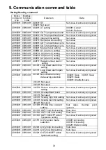
Page 32: ...50H 03H 06H 0010H Loop break alarm time setting Set value Decimal point ignored 20H 50H 03H 06H 0011H Loop break alarm span setting Set value Decimal point ignored 20H 50H 03H 06H 0012H Non volatile memory data saving selection 0000H Save 0001H Save 0002H Save 0003H Unable to save 0013H Not used 0014H Not used 20H 50H 03H 06H 0015H Sensor correction value setting Set value Decimal point ignored 20...

Page 33: ... A2 action delayed timer setting Set value 20H 50H 03H 06H 002BH A3 action delayed timer setting Set value 20H 50H 03H 06H 002CH A4 action delayed timer setting Set value 20H 50H 03H 06H 0037H Control Allowed Prohibited selection 0000H Control Prohibited 0001H Control Allowed 20H 50H 03H 06H 0038H Control Allowed Prohibited selection when power on 0000H Control Prohibited when power on 0001H Contr...

Page 34: ...045H Direct Reverse action selection 0000H Reverse action Heating 0001H Direct action Cooling 0046H Not used 20H 50H 03H 06H 0047H AT bias setting Set value Decimal point ignored 20H 50H 03H 06H 0048H ARW anti reset windup Set value 20H 50H 03H 06H 0049H A3 action selection 1 The same as Alarm 1 action selection p 33 20H 50H 03H 06H 004AH A4 action selection 1 The same as Alarm 1 action selection ...

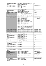
Page 35: ...FF 1 ON 25 digit A4 output 0 OFF 1 ON 26 digit Heater burnout alarm output 1 0 OFF 1 ON When sensor is burnt out 0 OFF 27 digit Loop break alarm output 0 OFF 1 ON 28 digit Overscale 0 OFF 1 ON 29 digit Underscale 0 OFF 1 ON 210 digit Actuator short circuit alarm output 1 0 OFF 1 ON 211 digit During AT 0 OFF 1 AT 212 digit Heater burnout alarm output 2 0 OFF 1 ON When sensor is burnt out 0 OFF 213 ...

Page 36: ...ted as a whole number and expressed in hexadecimal figures Data item 1 When the alarm action type is changed during Alarm 1 2 3 4 action selection the alarm setting value returns to the default value The alarm output A1 and status flag A1 A2 A3 A4 are also initialized 2 Selects whether to turn the control output OUT1 and cooling output OUT2 ON or OFF when the PV goes outside the control range 3 In...

Page 37: ...on 10 2 Start running Table 10 1 1 Setting item Setting range Default value SV Scaling low limit value to Scaling high limit value 0 AT setting 0000H Cancel 0001H Perform 0000H Cancel OUT1 proportional band setting 0 0 to 110 0 2 5 OUT2 proportional band setting 0 0 to 10 0 times OUT1 proportional band 1 0 times Integral time setting 0 to 1000s 200s Derivative time setting 0 to 300s 50s ARW settin...

Page 38: ...me as Alarm 1 action selection 0000H No alarm Alarm 3 action selection The same as Alarm 1 action selection 0000H No alarm Alarm 4 action selection The same as Alarm 1 action selection 0000H No alarm Alarm 1 hysteresis setting 0 1 to 100 0 For DC input 1 to 1000 1 0 Alarm 2 hysteresis setting 0 1 to 100 0 For DC input 1 to 1000 1 0 Alarm 3 hysteresis setting 0 1 to 100 0 For DC input 1 to 1000 1 0...

Page 39: ...0EH JPt100 200 to 500 000FH K 320 to 2500 0010H K 199 9 to 932 0 0011H J 320 to1800 0012H R 0 to 3200 0013H S 0 to 3200 0014H B 0 to 3300 0015H E 320 to 1500 0016H T 199 9 to 750 0 0017H N 320 to 2300 0018H PL 0 to 2500 0019H C W Re5 26 0 to 4200 001AH Pt100 199 9 to 999 9 001BH JPt100 199 9 to 900 0 001CH Pt100 300 to 1500 001DH JPt100 300 to 900 001EH 4 to 20mA DC 1999 to 9999 001FH 0 to 20mA DC...

Page 40: ...rect Cooling action 0000H Reverse Heating AT bias setting 0 to 50 0 to 100 or 0 0 to 50 0 0 0 to 100 0 For DC input Not available 20 Output status selection when input abnormal 0000H Output OFF 0001H Output ON 0000H Output OFF Table 10 1 2 Alarm action Setting range High limit alarm Scaling span to Scaling span Low limit alarm Scaling span to Scaling span High Low limits alarm 0 to Scaling span Hi...

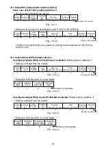
Page 41: ...ut from DC voltage to other inputs remove the sensor connected to this unit first then change for the input Header 21H 50H 02H 1 1 1 30H 30H 34H 34H 4 44H 35H 03H 2 1 20H 1 30H 30H 30H 42H 4 Address Sub address Command type Data item Data Checksum Delimiter Number of characters 21H 06H 1 1 44H 46H 03H 2 1 Header Address Checksum Delimiter Number of characters Header 21H 50H 02H 1 1 1 30H 30H 32H 3...

Page 42: ...ontrol Allowed Prohibited selection when power on 0038H control starts so as to maintain the control target at the SV If Control Prohibited is selected the unit switches to standby status and does not perform control action after the power is turned on During running when Control Allowed is selected during Control Allowed Prohibited selection 0037H control starts so as to maintain the control targ...

Page 43: ...normal status Fig 10 4 4 21H 20H 02H 1 1 1 30H 30H 38H 31H 4 44H 36H 03H 2 1 20H 1 Header Address Sub address Command type Data item Checksum Delimiter Number of characters Header 21H 20H 06H 1 1 1 30H 30H 38H 31H 4 46H 42H 03H 2 1 20H 1 30H 31H 46H 34H 4 Address Sub address Command type Data item Data Checksum Delimiter Number of characters Header 21H 50H 02H 1 1 1 30H 30H 33H 37H 4 45H 34H 03H 2...

Page 44: ...Error code 4 Unsettable status is returned If auto tuning is canceled during process P I D and ARW values return to values set before the auto tuning was performed If auto tuning has not finished 4 hours after it has started it is automatically finished If power failure occurs during PID auto tuning the auto tuning stops Header 21H 50H 02H 1 1 1 30H 30H 30H 33H 4 45H 42H 03H 2 1 20H 1 30H 30H 30H ...

Page 45: ...ID constant 2 PID constant calculated 3 Controlled by the PID constant set by auto tuning Fig 10 5 2 3 In the case of a large difference between the setting value and processing temperature as the temperature is falling When AT bias is set to 20 the AT process will fluctuate at the temperature 20 higher than the setting value 1 Calculating PID constant 2 PID constant calculated 3 Controlled by the...

Page 46: ...al time I Integral action is used to eliminate offset When the integral time is shortened the returning speed to the setting point is accelerated However the cycle of oscillation is also accelerated and the control becomes unstable 3 Derivative time D Derivative action is used to restore the change in the processing temperature according to the rate of change It reduces the amplitude of overshoot ...

Page 47: ...iation Proportional band Proportional band Control action Unlit Lit Open collector output C M Relay contact output R M Non contact voltage output S M DC current output A M Lit Unlit Cycle action is performed according to deviation Cycle action is performed according to deviation Cycle action is performed according to deviation Cycle action is performed according to deviation Cycle action is perfor...

Page 48: ...ay contact output DC current output 4mA DC ON OFF SV setting ON OFF Hysteresis Hysteresis 4mA DC 20mA DC 20mA DC 4 5 4 5 4 5 4 5 4 5 4 5 4 5 4 5 SV setting Indicator OUT Green Lit Unlit Unlit Lit Non contact voltage output 0V DC 12V DC 0V DC 12V DC 4 5 4 5 4 5 4 5 Open collector output C M OFF ON OFF ON 4 5 4 5 4 5 4 5 A M S M R M ...

Page 49: ...e output S M DC current output A M OFF ON OFF ON Open collector output C M Cycle action is performed according to deviation Cycle action is performed according to deviation 20mA DC 20 to 4mA DC 4mA DC 4 5 4 5 4 5 4 5 4 5 4 5 Lit Unlit Green Indicator OUT 12V DC 12 0V DC 0V DC 4 5 4 5 4 5 ON 6 7 ON OFF 6 7 OFF 6 7 OUT2 P band OFF ON Cooling action SV setting DC Cycle action is performed according t...

Page 50: ...2 P band OFF ON OFF ON Control action Cooling action Heatng action SV setting Cycle action is performed according to deviation Relay contact output R M Unlit 4 5 4 5 4 5 4 5 4 5 4 5 20mA DC 20 to 4mA DC 4mA DC Lit OUT Green Indicator Cycle action is performed according to deviation 4 5 4 5 4 5 12V DC 12 0V DC 0V DC Cycle action is performed according to deviation 4 5 4 5 4 5 ON ON OFF OFF Cycle ac...

Page 51: ... 5 4 4mA DC 5 4 7 6 OFF ON 7 6 OFF 7 6 ON DC C M 5 4 ON 5 4 ON OFF 5 4 OFF OUT OUT1 P band OUT2 P band Overlap band Heating action Cooling action Control action Relay contact ouput Non contact voltage ouput DC current output Open collector output Cycle action is performed according to deviation Changes continuously according to deviation Indicator Green Lit Unlit Cycle action is performed accordin...

Page 52: ...oint Alarm 1 set point Alarm 1 set point Alarm 1 set point Alarm 1 set point Alarm 1 set point Alarm 1 set point Alarm action Alarm action Alarm action High limit alarm with standby Low limit alarm with standby side side side side Alarm 1 set point Alarm 1 set point Alarm 1 set point Alarm 1 set point Alarm 1 set point Alarm 1 hysteresis Alarm 1 hysteresis Alarm 1 hysteresis Alarm 1 hysteresis Ala...

Page 53: ...nnot be outputted OFF ON 7 6 7 6 ON OFF OFF ON 7 6 7 6 OFF ON Heater burnout alarm action Small Large Heater burnout alarm set point Load current Heater burnout alarm output Heater burnout alarm set point Load current Actuator short circuit alarm action Actuator short circuit alarm output Small Large OFF ON High Low limits alarm with standby SV setting Alarm 1 set point set point Alarm action Alar...

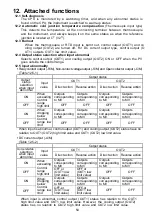
Page 54: ...onding to MV Outputs corresponding to MV Outputs corresponding to MV OFF When exceeding Control range high limit OFF OFF OFF OFF ON Outputs corresponding to MV Outputs corresponding to MV Outputs corresponding to MV Outputs corresponding to MV OFF When dropping below Control range low limit OFF OFF OFF OFF When input is abnormal control output OUT1 and cooling output OUT2 status have no relation t...

Page 55: ...tion value 12 7 PV filter Reduces the effect of noise by including a first order lag filter in the PV 12 8 Power failure countermeasure The setting data is backed up in the non volatile IC memory 12 9 Non volatile memory data saving selection If Non volatile memory data Unable to save is selected during Non volatile memory data saving selection all setting values except for the input type selectio...

Page 56: ...eparately DC voltage V 0 to 1V DC Input impedance 1M or more Allowable input voltage 5V DC or less Allowable signal source resistance 2k or less 0 to 5V DC 1 to 5V DC 0 to 10V DC Input impedance 100k or more Allowable input voltage 15V DC or less Allowable signal source resistance 100 or less Supply voltage 24V DC Allowable voltage fluctuation 20 to 28V DC Ripple voltage 5 p p or less General stru...

Page 57: ...1 proportional band P 0 0 to 110 0 Default value 2 5 Integral time I 0 to 1000s Off when set to 0 Default value 200s Derivative time D 0 to 300s Off when set to 0 Default value 50s OUT1 proportional cycle 1 to 120s Default value R M 30s S M 3s C M 3s A M Not available ARW 0 to 100 Default value 50 Manual reset Proportional band converted value Default 0 0 OUT1 ON OFF hysteresis 0 1 to 100 0 Defaul...

Page 58: ...Setting range High limit alarm Scaling span to Scaling span Low limit alarm Scaling span to Scaling span High Low limits alarm 0 to Scaling span High Low limit range alarm 0 to Scaling span Process high alarm Scaling low limit to Scaling high limit value Process low alarm Scaling low limit to Scaling high limit value High limit alarm with standby Scaling span to Scaling span Low limit alarm with s...

Page 59: ...0 DC input 0 to 1500 Output Open collector Control capacity 0 1A 24V DC Serial communication Cable length 1 2km Maximum Cable resistance Within 50 The terminator is not necessary or 120 or more on one side of the cable Communication line Based on EIA RS 485 Communication method Half duplex communication Communication speed 9600bps 4800 9600 19200bps Selectable by DIP switch Synchronous system Star...

Page 60: ...ness 3m 1 length CT CTL 6S 1 piece For W 100A option Wire harness 3m 1 length CT CTL 12 S36 10L1 1 piece For W3 20A option Wire harness 3m 2 lengths CT CTL 6S 2 pieces For W3 100A option Wire harness 3m 2 lengths CT CTL 12 S36 10L1 2 pieces 13 2 Optional specifications Heater burnout alarm Actuator short circuit alarm Option code W single phase W3 3 phase This alarm cannot be applied to DC current...

Page 61: ...tivated Actuator short circuit alarm 2 W3 option When control output is OFF and if CT2 input value detected current is higher than Heater burnout alarm 2 set value this alarm is activated If CT2 input value detected current is lower than Heater burnout alarm 2 set value this alarm will not be activated Heater burnout alarm 1 2 Actuator short circuit alarm 1 2 Fig 13 2 1 Fig 13 2 2 CT connection fo...

Page 62: ...top bit of the master do not accord with those of the slave The instrument number address of the slave does not coincide with that of the command The instrument number address of the slave is duplicated in multiple slaves Though it is able to communicate the response is NAK Check whether a non existent command code has been sent The setting command data goes outside the setting range of the slave ...

Page 63: ...the instrument input terminals securely PV is low Check whether the input signal source for DC voltage 1 to 5V DC or DC current 4 to 20mA DC is disconnected How to check whether the input signal wire is disconnected DC voltage 1 to 5V DC If the input to the input terminals of the instrument is 1V DC and if a scaling low limit value is indicated the instrument is likely to be operating normally how...

Page 64: ...ar the control unit Keep equipment that interferes with or makes noise away from the control unit For further inquiries please consult our agency or the shop where you purchased the unit No NCL11E2 2005 03 SHINKO TECHNOS CO LTD OVERSEAS DIVISION Reg Office URL E mail 2 5 1 Senbahigashi Minoo Osaka Japan http www shinko technos co jp overseas shinko technos co jp Tel Fax 81 72 727 6100 81 72 727 70...

Reviews: