background image

T o Use The Pulley Block: 

1. With the Winch Cable Hook (Part# 57) and the accessory Pulley Block Assembly

(part# 56) attached to the Steel Cable, the Pulley Block Assembly (part# 56) can be   
used to nearly double the Winch’s capacity by simply attaching the Pulley Block  
Assembly (part# 56) directly to the load and the Winch Cable Hook (part# 57) to  
a sturdy  mount near the Winch (such as the rear bumper). 

(See Figure H.) 


2. To attach the Pulley Block Assembly (part# 56) to the Steel Cable, remove the two 

Nuts on the Pulley Hook. Then, remove one Side Plate on the Pulley Hook.  

(See 

Figure H.) 

3. Insert the Steel Cable beneath the Pulley. Then, reattach the Side Plate and the 

two Nuts.  

(See Figure H.) 

WINCH CABLE 

HOOK (#57) 

FIGURE H 

BUMPER 

SIDE 

PLATE 

NUT 

PULLEY 

INSERT 

STEEL 

CABLE HERE 

PULLEY 

Pulley Block Assembly (#56) 

AT TA CH PULLEY BLOCK 

ASSEMBLY (#56) TO LOAD

10 

Summary of Contents for fantom U0705

Page 1: ...12 VOLT WINCH 12 VOLT WINDE POWER IN POWER OUT Assembly and Operating Instructions Bedienungsanleitung und Gebrauchsvorschriften Model U0705 SHINN FU EUROPE B V Roosendaal The Netherlands ...

Page 2: ...ad damge to the winch property damage personal or fatal injury 2 Warning information shall be emphasized and understood If the user is not fluent in English instructions and warnings shall be read to and discussed with the user in the user s native language by the owner to make sure that user comprehends the contents 3 The owner shall retain this manual for further reference to important warnings ...

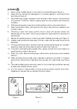
Page 3: ...or a heavy rag when handling the cable see Figure 3 8 Always keep hands and body away from the cable and the cable spool during operation 9 For best winching results a vehicle should be running transmisstion set in neutral emgerncy brake set and wheels securely choked see Figure 4 10 To prevent overheating and possibly a fire always connect the circuit breaker to positive battery cable of the winc...

Page 4: ... a truk trailer or other suitable location 2 Align the Base of the Winch with the desired location and mark for drilling the three mounting holes required to attach the Winch to the desired location Then drill these three mounting holes on the vehicle trailer See Figure A 3 Use three hardened Steel Bolts at least 3 8 in diameter three Lock Washers and three Nuts all nor included to securely attach...

Page 5: ...B 2 Insert the heads of the three screws part 74 into the three keyhole slots on the Base of the Winch See Figure B 3 Attach the Winch with its Plate part 75 to the vehicle s Hitch Ball not included by inserting the Hitch Ball through the teardrop shaped hole in the Adapter Plate See Figure B 5 SCREW 74 WASHER 76 ADAPTER PLATE 75 NUT 77 W E I V M O T T O B W E I V E D I S HITCH BALL NOT INCLUDED P...

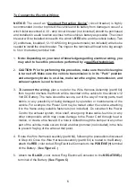
Page 6: ...t system is cool to touch 3 To connect the wiring plan a route for the Wire Harness Assembly part 64 from he point of where the Winch will be mounted on the vehicle to the vehicle s 12 Volt DC Battery The route should be secure out of the way of moving parts road debris or any possibility of being damaged by operation or maintenance of the vehicle For example the Power Cord nay be routed under the...

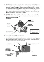
Page 7: ...h or around a Battery 7 CAUTION Carbon Monoxide is a colorless odorless vapor emitted from the engine s exhaust and may kill or injure when inhaled Do not run the engine in an enclosed area To Connect The Handheld Remote Control 1 Lift the Rubber Seal on the left side of the Winch and insert the Cord Plug part 8 into the Remote Control Socket Then set the Remote Control Housing in a safe place unt...

Page 8: ...ersonal injury See Figure E 2 Place the vehicle s transmission in Park Turn off the engine Set the emergency brake and block the wheels from rolling using suitable chocks not included 3 To operate the Hand Crank part 1 turn the Clutch Knob clockwise until hand tight Do not force it or overtighten See Figure E 4 Rotate the Hand Crank part 1 clockwise to tighten the Steel Cable Continue turning the ...

Page 9: ...Part 32 and Control Knob B Part 43 the wheels from rolling using suitable chocks not included 3 NOTE You may wish to keep the vehicle s engine running while using the Winch to continually recharge the battery However use extreme caution when working around a vehicle with its engine running 4 Pull out the Steel Cable to the desired length using the Power Out feature located on the Switch part 10 Al...

Page 10: ...Cable Hook part 57 to a sturdy mount near the Winch such as the rear bumper See Figure H 2 To attach the Pulley Block Assembly part 56 to the Steel Cable remove the two Nuts on the Pulley Hook Then remove one Side Plate on the Pulley Hook See Figure H 3 Insert the Steel Cable beneath the Pulley Then reattach the Side Plate and the two Nuts See Figure H WINCH CABLE HOOK 57 FIGURE H BUMPER SIDE PLAT...

Page 11: ...e gears every six months To do this remove the clutch knob and separate the left and right housing Use any marine type grease PLEASE READ THE FOLLOWING CAREFULLY THE MANUFACTURER AND OR DISTRIBUTOR HAS PROVIDED THE PARTS LIST AND ASSEMBLY DIAGRAM IN THIS MANUAL AS A REFERENCE TOOL ONLY NEITHER THE MANUFACTURER OR DISTRIBUTOR MAKES ANY REPRESENTATION OR WARRANTY OF ANY KIND TO THE BUYER THAT HE OR ...

Page 12: ...chlagen zu können BESCHREIBUNG Die elektrische Seilwinde ist für verschiedene Zwecke vorgesehen wie Ziehen Stellen und Abladen und ist mit Power in und Freilauf Kabelfunktionen ausgerüstet Sie ist für zeitweiligen Gebrauch entworfen und hat eine spezifische Reihe von Möglichkeiten siehe Spezifikationen Die Fantom 12 Volt Seilwinde ist tragbar darf aber nicht für Hebelasten benutzt werden nicht für...

Page 13: ...s Tuch wenn Sie am Kabel arbeiten siehe Abbildung 3 8 Bleiben Sie mit Ihren Händen und Ihrem Körper aus der Nähe der Kabelspule 9 Für die besten Resultate des Ziehens soll der Motor des Fahrzeugs laufen die Transmission im Freistand stehen die Handbremse fest und die Räder blockiert sein siehe Abbildung 4 10 Um einer Überhitzung oder einem möglichen Brand vorzubeugen soll man immer den Sicherung a...

Page 14: ...neten Stelle auswählen 2 Die Winde an der ausgewählten Befestigungsstelle ausrichten und die Stellen markieren an denen die 4 Löcher für das Untergestell der Winde gebohrt werden sollen 3 Die Löcher an diesen Stellen in das Fahrzeug bohren 4 Die Winde mit entsprechenden Schrauben aus gehärtetem Stahl befestigen 8 8 Zeitweise Anbringung 1 Mit den mitgelieferten Muttern die 3 Stiftschrauben auf die ...

Page 15: ...n 2 Eine Route für die Verkabelung von der Stelle des Fahrzeuges an der die Winde befestigt oder verwendet wird bis zur Batterie festlegen Diese Route muß sicher sein sich bewegende Teile und auf der Straße befindliche Gegenstände umgehen und jede Möglichkeit ausschließen daß die Kabel durch den Betrieb oder die Wartung des Fahrzeuges beschädigt werden Es wäre zum Beispiel möglich die Leiter unter...

Page 16: ...er Fernbedienung betätigen und mit leichter Spannung von der Spule ziehen Immer mindestens drei Seilwindungen auf der Spule lassen um zu verhindern dass das Seil aus der Winde gezogen wird 3 Seil über ein Zugseil eine Kette oder auf andere geeignete Weise am zu ziehenden Gegenstand einhaken Nie das Seil um den Gegenstand legen und dann direkt am Seil einhaken da dadurch der zu ziehende Gegenstand ...

Page 17: ...die Winde kontrollieren zu lassen in einem ortlichen Service Center und daß die kaputten Teile durch originale Fantom Ersatzteile ersetzt werden 1 Ölen Sie regelmäßig oder mehrmals bei regelmäßigem Gebrauch 2 Schmieren Sie ein wenig Fett auf die beweglichen Teile etwa alle sechs Monate Dafür entfernen Sie den Kupplungsknopf und öffnen Sie beide Hälften des Gehäuses Benutzen Sie Handelsübliges Indu...

Page 18: ...705 U0705 WHA Wire Harness Assembly U0705 WCH Winch Cable Hook U0705 HC Hand Crank U0705 PL Plate U0705 HRC Handheld Remote Control U0705 GS1 Gear set 1 U0705 GS2 Gear set 2 U0705 GS4 Gear set 4 U0705 GS3 Gear set 3 U0705 MT Motor ...

Page 19: ...ken U0705 HC Handkurbel U0675 PL Platte U0705 GS3 Radsatz 3 U0705 GS1 Radsatz 1 U0705 GS2 Radsatz 2 U0675 HRC Fernbedienung U0705 WHA Drahtkabelstrang U0705 MT Motor Ersatzteile liste Modell Nr U0705 U0705 GS4 Radsatz 4 ...

Page 20: ...ed and shown for illustration purposes only and are not available individually as replacement parts U0705 Anmerkung Nicht alle Bestandteile der Winde sind Ersatzteile aber sie werden in der auseinandergezogenen Darstellung als Bezugspunkt für die richtige Positionierung ausgezeigt ...

Page 21: ...0 51 52 53 54 55 56 57 58 59 60 61 62 63 64 65 66 67 68 Nut Mutter M 12 Washer Scheibe 12 Retaining Ring Seegerring 42 Bearing Wellenlager Washer Scheibe 15 Plate Platte Cable Collar Kabelkrangen Plate 2 Platte 2 Washer Scheibe 20 Bearing Wellenlager Retaining Ring Seegerring 15 Drive Gear Antriebszahnrad Spring Washer Federscheibe 20 Nut Mutter M 20 Retaining Ring Seegerring 10 Washer Scheibe 10 ...

Page 22: ... Shinn Fu Europe B V DÉCLARATION DE CONFORMITÉ F Conformément à la directive CE EMC le soussigné étant mandataire de Shinn Fu Europe B V Roosendaal Pays Bas déclare à la responsabilité exclusive de la firme mentionnée ci dessus que les modèles ont énuméré ci dessous et sa variante proches pour lesquels vaut cette déclaration répondent aux exigences de sécurité et de santé de la directive CE EMC à ...

Reviews: