-21-
Model M1117 (For Machines Mfd. Since 9/21)
O
PE
R
ATIO
NS
Adjusting.Front.Work.Stop
The front work stop keeps the shearing blades from
pushing the workpiece forward during cutting operations.
Use the following steps to adjust the front work stop
to the front workpiece edge once the workpiece has
been inserted under the blade guard and is ready to be
sheared.
To.adjust.front.work.stop,.do.these.steps:
1..
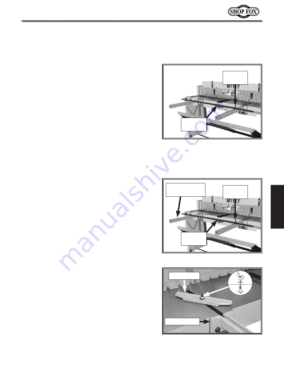
Loosen (2) front work stop wing nuts (see
Figure
19
).
2..
Adjust front work stop against front workpiece edge
and tighten wing nuts to secure.
Figure.19.
Location of front work stop
wing nuts.
Front
Work Stop
Wing Nut
(1 of 2)
Using.Bevel.Gauge
The bevel gauge can be installed in place of the front
work stop to support workpieces that have an angled
front edge.
To.use.bevel.gauge,.do.these.steps:
1..
Loosen (2) front work stop wing nuts (see
Figure
20
).
2..
Slide front work stop out of front extension arms to
remove (see
Figure
20
).
3..
Position workpiece on table and under blade guard
for shearing operation.
Figure.20.
Front work stop components.
Front
Work Stop
Wing Nut
(1 of 2)
Front Extension
Arm (1 of 2)
4..
Install (1) M12-1.75 x 45 T-bolt in T-slot and secure
bevel gauge to extension arm or table against
workpiece front edge with (1) 12mm flat washer and
M12-1.75 wing nut (see
Figure
21
).
Note:
Figure 21
shows bevel gauge installed in left
T-slot, but it can be installed in either side. Install
the bevel gauge in the best position to secure your
workpiece for the operation.
Figure.21.
Bevel gauge installed to
support angled front workpiece edge.
Bevel Gauge
Extension Arm
4..
Tighten micro-adjustment lock knobs to secure rear
work stop position.
Summary of Contents for M1117
Page 40: ......


