-32-
Model M1117 (For Machines Mfd. Since 9/21)
SE
RV
IC
E
Adjusting.
Hold-Down/Blade.Guard
When the upper blade is lowered, the blade guard is also
engaged to contact and secure the workpiece during the
cutting operation. The blade guard must be parallel with
the table to correctly secure workpieces.
Tools.Needed.
Qty
Feeler Gauge Set ...............................................1
Wrench or Socket 19mm .......................................1
Adjusting.Blade.Guard.Clearance
For an extra thin or thick workpiece, the guard can be
adjusted for the correct amount of clearance to secure it.
To.adjust.blade.guard.clearance,.do.these.steps:
1..
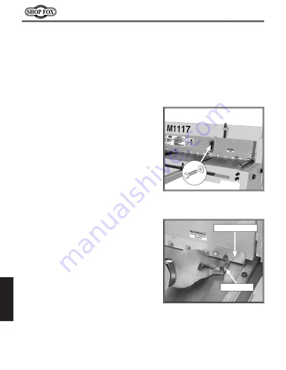
Loosen (2) blade guard hex bolts (see
Figure
33
).
2..
Adjust blade guard up or down to accommodate
workpiece thickness.
3..
Tighten (2) blade guard hex bolts to secure.
4..
Place edge of workpiece under blade guard, then use
foot pedal to confirm workpiece is secured by guard.
5..
Refer to following section to verify guard parallelism.
Figure.33.
Location of blade guard hex
bolts.
x 2
Adjusting.Blade.Guard.Parallel.With.Table
1..
Use foot pedal to lower and hold blade guard in
lowest position.
2..
Insert largest feeler gauge that will fit between
hold-down finger and table on right end of blade
guard (see
Figure
34
).
3..
Repeat
Step 2 on left end of blade guard.
— If both hold-down fingers are same distance from
table, no adjustment is required.
— If both hold-down fingers are not same distance
from table, proceed to
Step 4.
4..
Loosen blade guard hex bolt on side of blade guard
that needs adjustment.
5..
Adjust blade guard until entire length is same
distance from table, then tighten hex bolt.
Figure.34.
Using feeler gauge to check
blade guard clearance.
Hold-Down Finger
Feeler Gauge
Summary of Contents for M1117
Page 40: ......


