-16-
Model M1117 (For Machines Mfd. Since 9/21)
SE
TU
P
Assembly
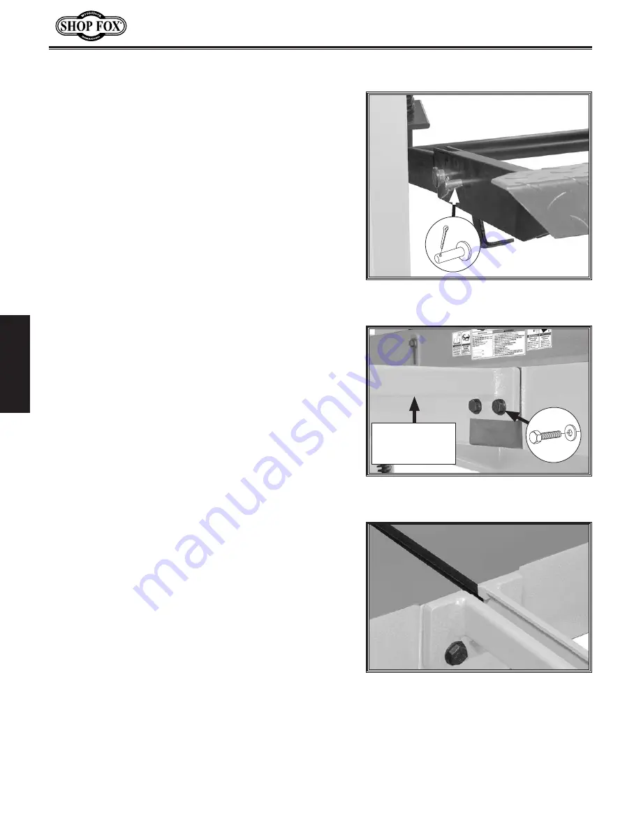
Figure.11.
Extension arm correctly
installed.
Before beginning the assembly process, refer to
Items.
Needed.for.Setup
and gather everything you need.
Ensure all parts have been properly cleaned of any
heavy-duty rust-preventative applied at the factory (if
applicable). Be sure to complete all steps in the assembly
procedure prior to performing the
Test.Run.
or connecting
the machine to power.
To.assemble.machine,.do.these.steps:
1..
Use level to check shear table.
— If table is level, no adjustment is required. Proceed
to
Step 2.
— If table is not level, use shims between floor and
base to level machine before proceeding. Leveling
shear helps blades and other components remain
straight and flat during life of machine so machine
can continue to cut straight and square.
2..
Cut cable ties securing foot pedal to table.
3..
Have another person press and hold foot pedal about
halfway through full range of movement.
4..
Insert (2) 12 x 45mm clevis pins in holes in foot
pedal frame and secure with (2) M3 x 50 cotter pins,
as shown in
Figure
9
.
Figure.9.
Location of hole in foot pedal
frame (1 of 2 shown).
x 2
5..
Attach (2) front extension arms to shear table with
(4) M12-1.75 x 30 hex bolts and 12mm flat washers
(see
Figure
10
).
Note:
Arm T-slots must line up with table T-slots,
and surfaces must be flush (see
Figure 11
).
Figure.10.
Front extension arms attached
to shear table.
Front
Extension Arm
(1 of 2)
x 4
Summary of Contents for M1117
Page 40: ......


