
-32-
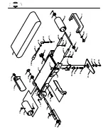
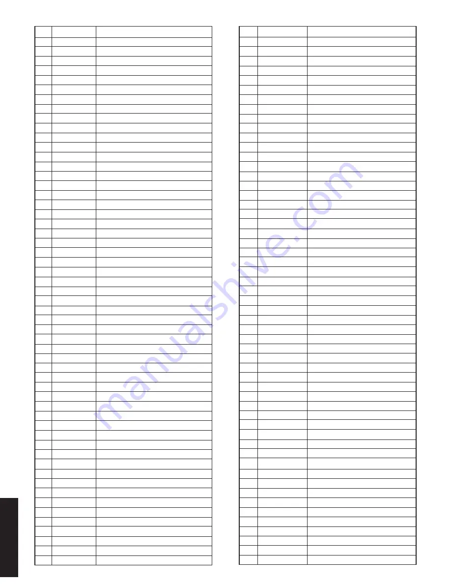
ref part # description
ref part # description
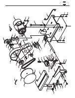
57 X1676057 SUPPORT
5
⁄
8
''-11 x 9''
58 X1676058 RUBBER FOOT
59
X1676059
IDLER ROLLER SHAFT
62A X1676062B
ROLLER ADJ BAR
64
X1676064
IDLER ROLLER
69
X1676069
MITER BODY
69A X1676069A PHILLIPS
®
SCREW 10-24 x
3
⁄
4
"
69B X1676069B PIN
1
⁄
4
"
70 X1676070 SCALE
71
X1676071
POWER CORD
77 XPAW04M
ALLEN
®
WRENCH 4MM
80 XPK23M
KEY 5 X 5 X 25
81A X1676081A
ROCKER ARM
82A X1676082A
LEVER, SHORT
83A X1676083A
ROCKER ARM
84A X1676084A ECCENTRIC
85A X1676085A
LEVER, LONG
86A X1676086A KNOB,
3
⁄
8
"-16
87A X1676087A SPACER
88A XPB21
HEX BOLT
3
⁄
8
"-16 x
3
⁄
4
"
89
XPSB31
CAP SCREW 10-24 x
5
⁄
8
"
90
X1676090
MOTOR CORD (1)
90A X1676090A
MOTOR CORD (2)
91
XPB16
HEX BOLT
3
⁄
8
"-16 x 1
1
⁄
2
"
92
XPW02
FLAT WASHER
3
⁄
8
"
93
X1676093
WASHER PLATE
94 X1676094 KNOB
95 XPLW01
LOCK WASHER
5
⁄
16
"
96 XPSS18 SETSCREW
5
⁄
16
"-18 x
3
⁄
4
"
97
XPW07
FLAT WASHER
5
⁄
16
"
98
XPN11
HEX NUT
3
⁄
8
''-24
99
X1676099
GRAPHITE PAD
100 X1676100
DUST PORT ABS
101 X1676101
FLAT WASHER
3
⁄
8
"
102 X1676102
DIRECTION SCALE
103 X1676103 POINTER
104 X1676104
LOGO
104A
X1676104A
LOGO SCREW
105 XPN08
HEX NUT
3
⁄
8
"-16
106 X1676106
HEX NUT 10-24
107 X1676107
PHILLIPS
®
SCREW
3
⁄
16
"-24 X
3
⁄
8
"
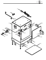
110 X1676110
CABINET
110A
X1676110A
CABINET DOOR
110B
X1676110B
DOOR LATCH SYSTEM
110C X1676110C
SHELF
111 X1676111
SWITCH HOUSING
112 X1676112
READ MANUAL WARNING
113 X1676113
MACHINE ID/WARNING
114 X1676114
IDLER ROLLER GUARD
115 X1676115
LOCK KNOB
118 X1676118
PHILLIPS
®
SCREW
3
⁄
16
"-24 X
3
⁄
8
"
119 X1676119
DUST PORT
120 X1676120
WIRE CONNECTOR
1
⁄
2
"
121 X1676121
ELECTRICITY WARNING
122 X1676122
UNPLUG WARNING
123 X1676123
SAFETY GLASSES WARNING
01 X1676001
DUST COVER
02 XPR03M
SNAP RING 12MM
02A XPR05M
SNAP RING 15MM
03 XP6201-2RS BALL BEARING 6201-2RS
03A XP6002-2RS BALL BEARING 6002-2RS
04 X1676004
DRIVE SHAFT
05 X1676005
SANDING BELT 6'' X 48''
06 XPK02M
KEY 5 X 5X 40
07 X1676007
SNAP RING 16MM
08 X1676008
SANDING BELT FRAME
09 X1676009
BACK STOP
10 XPSS02
SETSCREW
5
⁄
16
"-18 x
3
⁄
8
"
11 X1676011
DRIVE ROLLER
12 X1676012
HEX NUT
5
⁄
16
"-18
13 X1676013
5
⁄
16
" FLAT WASHER
14 X1676014
KNOB
15 X1676015
BEARING 6003-2RS
16 X1676016
COMPLETE MITER GAUGE ASSY
18 X1676018
CARRIAGE BOLT
5
⁄
16
"-18 x 1
1
⁄
4
"
19 X1676019
PULLEY COVER
20 X1676020
MITER BAR
20A X1676020A STUD
1
⁄
4
"
21 X1676021
CAST IRON DISC 10''
22 X1676022
SANDING DISC PAPER 10"
23 X1676023 TABLE
24 X1676024 TRUNNION
25 XPW06
FLAT WASHER
1
⁄
4
"
26 XPS04
PHILLIPS
®
SCREW
1
⁄
4
"-20 X
1
⁄
2
"
27 X1676027 PHILLIPS
®
SCREW 10-24 X
1
⁄
4
"
27A X1676027A PHILLIPS
®
SCREW 10-24 X
3
⁄
8
"
27B X1676027B FLAT WASHER
3
⁄
16
"
28 X1676028
TABLE POINTER
28A X1676028A MITER POINTER
28B X1676028B LOCK BRACKET
28C X1676028C LOCK PIN
29 X1676029
TABLE SUPPORT BRACKET
30 X1676030
SUPPORT BAR
32 XPB09
HEX BOLT
5
⁄
16
"-18 x
1
⁄
2
"
33 X1676033
TABLE MOUNT
34 X1676034
V-BELT 3L-240
35 X1676035 PULLEY
36 X1676036
MOTOR PULLEY
37 X1676037 KNOB
40 X1676040 BRACKET
41 XPB03
HEX BOLT
5
⁄
16
"-18 x 1"
42 XPSS03 SETSCREW
5
⁄
16
"-18 x
1
⁄
4
"
43 X1676043 MOTOR
44 X1676044
LOCK KNOB
45 X1676045
PLASTIC WASHER
1
⁄
4
"
46 X1676046
FLAT WASHER
3
⁄
16
"
49 X1676049
STRAIN RELIEF FITTINGS
51 X1676051
HEX NUT 10-24
52 X1676052 BASE
53 X1676053
SWITCH LOCK
53A X1676053A SWITCH
56 XPN04
HEX NUT
5
⁄
8
''-11
parts


