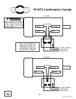
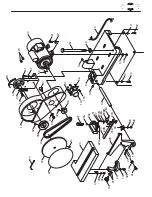
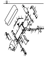
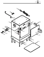
background image

-34-

Notes

Summary of Contents for SHOP FOX W1676

Page 1: ...734 3482 On Line Technical Support tech support woodstockint com COPYRIGHT 2001 BY WOODSTOCK INTERNATIONAL INC WARNING NO PORTION OF THIS MANUAL MAY BE REPRODUCED IN ANY SHAPE OR FORM WITHOUT THE WRIT...

Page 2: ...ls are Lead from lead based paints Crystalline silica from bricks cement and other masonry products Arsenic and chromium from chemically treated lumber Your risk from these exposures varies depending...

Page 3: ...ENERAL 13 SANDING UNIT TO BASE 14 IDLER ROLLER 14 SANDING DISC 14 BACK STOP 15 DUST PORTS 15 WORKING TABLE 16 QUICK RELEASE 16 4 ADJUSTMENTS 17 GENERAL 17 BELT TRACKING TENSION 18 19 IDLER GUARD 19 VE...

Page 4: ...stock International Inc is committed to customer satisfaction in providing this manual It is our intent to make sure all the information necessary for safety ease of assembly practical use and dura bi...

Page 5: ...This is Woodstock International Inc s sole written warranty and any and all warranties that may be implied by law including any merchantability or fitness for any particular purpose are hereby limite...

Page 6: ...rous environments Do not operate this machine in wet or open flame environments Airborne dust particles could cause an explosion and severe fire hazard 6 Ensure all guards are securely in place and in...

Page 7: ...mes to a complete stop before leaving the area 19 Perform machine maintenance and care Follow lubrication and accessory attachment instructions in the manual 20 Keep machine away from open flame Opera...

Page 8: ...rd to break Develop good habits and safety will become second nature to you 9 Sanding dust from some woods may be toxic or cause an allergic reaction Be sure to wear an appropriate respirator when wor...

Page 9: ...antee machine will be grounded Ground source must be verified The Shop Fox W1676 is prewired for 110 volts The motor supplied with your new machine is rated at 1 H P and will draw approximately 14 am...

Page 10: ...re 2 The electrical cord supplied with the W1676 does not come with a 220 volt plug Use a plug with a ground pin If your outlet does not accommodate a ground pin have it replaced by a qualified electr...

Page 11: ...gers close to moving disk Figure 4 Never use the right side of disk Upward rotation of disk can propel workpiece into the air Figure 6 Never place hands near back stop On small workpieces always use p...

Page 12: ...combined weight of the machine parts and the people moving them The W1676 represents a heavy load at 170 pounds Seek assistance before beginning assem bly ASSEMBLY INSTRUCTIONS Unpacking The Model W16...

Page 13: ...4 Cast Iron Disc 1 5 Idler Roller 1 6 Back Stop 1 7 Miter Gauge 1 8 Work Table 1 9 Table Support Rod 1 10 Quick Release Handle 1 11 Dust Port 1 12 Idler Roller Guard 1 13 Bolt Bag 1 14 21 2 Dia Dust P...

Page 14: ...ve been coated with an oil to prevent rust during shipment This oil needs to be removed before operation To remove the oil we recom mend using a solvent based degreaser Avoid using any chlorine based...

Page 15: ...le wrench 12mm open end wrench flathead screwdriver Phillips screw driver and 4mm Allen wrench Wear safety glasses dur ing the entire assembly process Failure to com ply may result in serious personal...

Page 16: ...ding unit to the stand Idler Roller Install the idler roller by inserting its flat axle ends into the slots on the ends of the adjust ments bar as shown in Figure 10 Sanding Disc The sanding disc is i...

Page 17: ...rts are designed to reduce the amount of dust on the sander and in the air Fasten the belt dust port to the sanding belt frame using 2 Phillips head screws as shown in Figure 13 Fasten the disc dust p...

Page 18: ...is facing the setscrews 3 Securely tighten the setscrews as shown in Figure 15 4 Slide the working table assembly onto the end of the support bar and securely tighten the setscrews located in the tabl...

Page 19: ...from 0 45 In all the Model W1676 will be a welcome addition to the home or commercial workshop The following section will go through the above adjustment steps Wear safety glasses dur ing the entire...

Page 20: ...either side the tracking needs to be adjusted 6 Turn the tracking knob 1 4 turn clockwise to adjust the sanding belt towards the tracking knob and turn counter clockwise to adjust the sanding belt awa...

Page 21: ...ase or decrease the belt tension 3 When the proper tension is achieved tight en the hex bolt that was loosened in Step 1 while maintaining the position of the eccen tric bolt with a wrench 4 Run the s...

Page 22: ...he sanding belt frame to the vertical position as shown in Figure 24 4 Tighten down the nuts that were loosened in Step 2 The working table can also be repositioned next to the vertical surface of the...

Page 23: ...you to leave the pul ley cover and working table attached Peel back half of the abrasive disc backing and slip the covered portion behind the closed pulley door Stick the peeled back portion of the a...

Page 24: ...29 3 Loosen the screw holding the angle indicator and set it to the 90 mark on the scale 4 Using a 90 square check to see if the miter slot is perpendicular to the sanding disc as shown in Figure 30 5...

Page 25: ...or vibrations shut the machine off immediately The machine should not be run any further until the problems are corrected 4 Unplug the machine and investigate the source of the noise or vibration Do n...

Page 26: ...to hold the workpiece securely when the back stop is removed as shown in Figure 33 Curved Sanding Concave curves can be sanded on the idler roller 1 Remove the idler roller guard from the sander 2 Hol...

Page 27: ...s set at an angle the gap between the disc and the table becomes greater Figure 37 therefore use extra care to prevent small pieces and fingers from becoming lodged in the gap Only use the left half o...

Page 28: ...ch time you use it Check for the following conditions and repair or replace when necessary 1 Loose mounting bolts 2 Worn switch 3 Worn or damaged cords and plugs 4 Damaged sanding belts or discs 5 Any...

Page 29: ...regarding Woodstock International Inc s warranty and return policy Should a problem arise we recommend that you keep your proof of purchase with your manual If you need additional technical informatio...

Page 30: ...VOLT GREEN GROUND TO 220 VOLT POWER SUPPLY NOTE THE WIRES FROM THE POWER SUPPLY BESIDES THE GREEN GROUND WIRE ARE INTERCHANGABLE THEREFORE COLORS ARE NOT SPECIFIED 6A 2001 Woodstock International Disc...

Page 31: ...2 90 41 41 97 37 80 52 45 69 27 28A 20 29 33 33 25 25 26 26 27 13 32 24 97 14 28 10 96 44 23 30 10 19 42 10 21 22 34 35 97 32 32 42 36 97 40 93 18 32 13 32 13 119 118 51 43 46 120 27B 28B 28C 27A 69A...

Page 32: ...1 2A 94 98 99 86A 100 3A 5 96 96 95 12 11 4 6 13 9 8 41 103 15 7 2 2 3 3 59 62A 106 89 62A 25 115 114 64 105 105 82A 85A 102 81A 83A 101 87A 88A 84A 92 91 B B 106 89 107...

Page 33: ...110 104 90A 27 46 51 111 53A 53 104A 58 71 41 13 12 113 112 121 122 123 110B 110B 110A 49 110C...

Page 34: ...76120 WIRE CONNECTOR 1 2 121 X1676121 ELECTRICITY WARNING 122 X1676122 UNPLUG WARNING 123 X1676123 SAFETY GLASSES WARNING 01 X1676001 DUST COVER 02 XPR03M SNAP RING 12MM 02A XPR05M SNAP RING 15MM 03 X...

Page 35: ...33 Notes...

Page 36: ...34 Notes...

Page 37: ...___________________________________________________ __________________________________________________________ 1 Where did you purchase your Shop Fox machine __________________________________________...

Page 38: ...TAPE ALONG EDGES PLEASE DO NOT STAPLE FOLD ALONG DOTTED LINE FOLD ALONG DOTTED LINE WOODSTOCK INTERNATIONAL INC P O BOX 2309 BELLINGHAM WA 98227 2309 Place Stamp Here...

Reviews: