background image

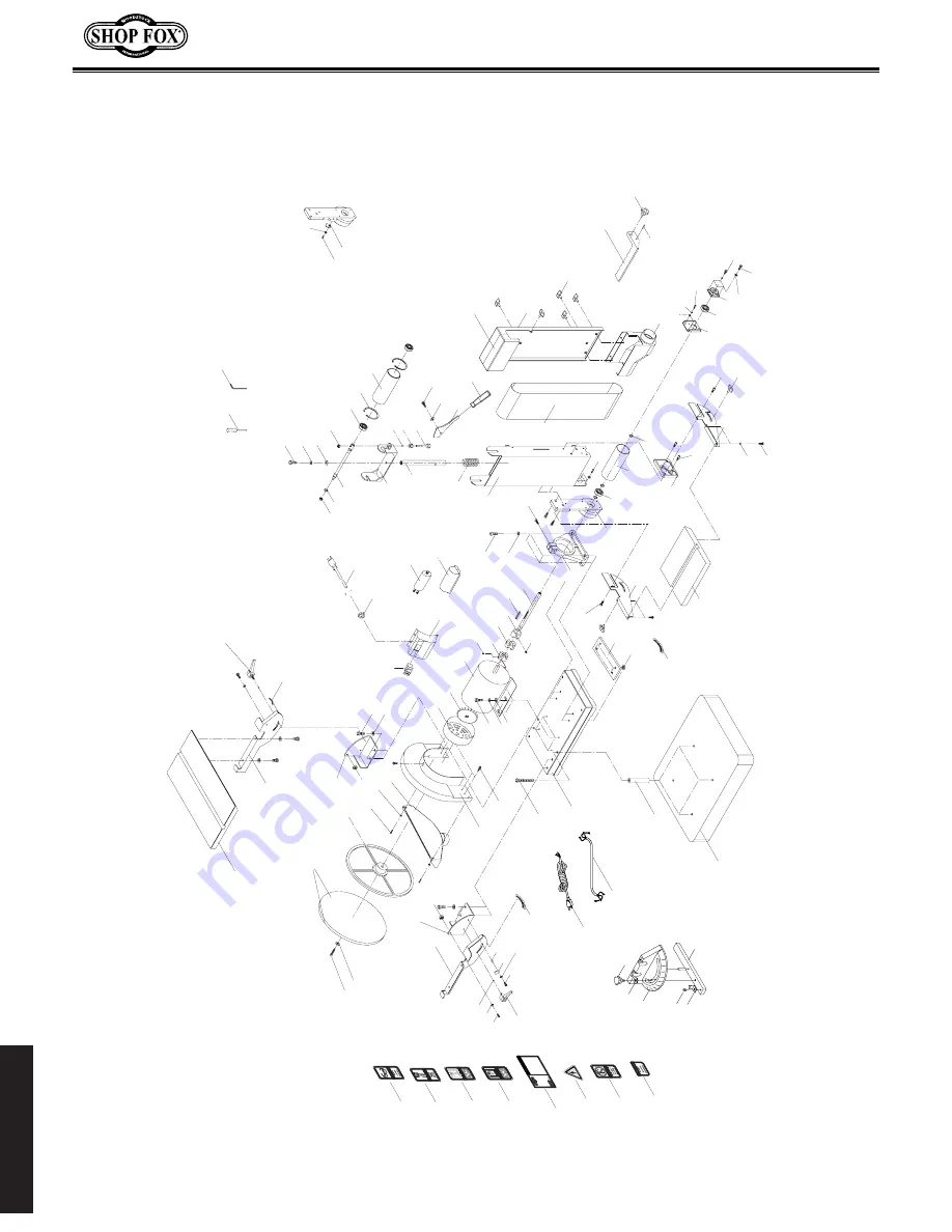
PARTS

-24-

PARTS

1

2

81

89

69

65

55

14

20

15

27

28

33

45

64

72

80

34

17

11

16

64

13

73

46

69

33

64

43

52

64

47

46

48

75

60

66

32

23

32

25

49

62

60

90

61

57

58

57

29

23-6

74

44

42

41

40

38

50

51

35

53

36

37

85

86

26

39

58

82

37

68

67

68

80

66

57

18

12

73

66

68

18

5

9

70 

8

4

10

22

71

3

21

56

87

58

83

59

7

12

78

78

80

54

84

84

91

63

19

54

79

21

92

93

23-1   

23-2

23-3

23-4      

23-5  

111

100

99

96

95

97

98

FAILU

R

E TO FOLL

O

W TH

ESE W

AR

NINGS

 W

ILL

 RE

SUL

T IN 

SER

IOUS PERS

ONAL INJU

RY:

  1

RE

AD A

ND U

N

DERS

TAND

 M

A

NUA

L BE

F

OR

E S

T

ARTING

 M

ACH

INE.

  2

ALW

AY

S WE

AR E

YE

 PR

OT

ECTIO

N.

  3

.

ALW

AYS

 WEA

R A

N A

PPR

OVED D

US

T MA

SK 

OR

 RE

SP

IRATO

R

.

  4. 

PLU

G POW

E

R C

OR

D IN

TO

 GR

OUN

DE

D O

UTL

E

T O

N

LY.

  5. 

DO

 N

OT

 WEA

R

 LOOS

CLOT

H

ING, G

LOVES OR

 JEWEL

RY. ROLL 

UP OR

 BU

TT

ON

 LO

N

G S

LEEVE

S, AN

D TIE

 B

A

CK LON

G H

AIR

.

  6. 

DO NO

T U

SE 

UND

ER 

THE

 IN

FLU

EN

CE

 OF D

RUG

OR ALC

OHO

L, 

OR

 IF

 EX

CESSIV

ELY 

T

IR

ED.

  7.

O

NLY OP

ERA

TE M

ACH

INE

 ON FL

AT

, LEV

EL G

ROU

ND.

  8

.

MA

K

E SU

R

E M

A

CH

IN

E IS

 SET U

P A

ND A

D

JU

STED

 C

ORR

EC

TLY 

BEFO

R

E B

EGI

NN

IN

G OPERA

TIO

N.

  9.

DO

 N

OT TOUC

H SA

ND

ING

 S

PIN

D

LE WH

ILE 

IT

 IS IN MO

TIO

N.

 10.

DO

 N

OT 

SAND

 WOO

WIT

H LO

O

SE KNOT

S/LA

RGE

 SPLINTER

S.

 11.

ALW

AY

S SAND A

G

AINST

 TH

E R

OT

A

TION

 O

F TH

E S

PIN

DL

E.

 12.

M

A

INT

A

IN A

 FI

RM, C

ONT

R

OL

LED

 GR

IP 

ON 

THE W

ORK

PIEC

E.

 13.

U

S

E H

OLDIN

G

 JI

GS

 OR

 CLA

MPS FO

R SMA

LL

 W

O

RK

PIECES

.


 14

.

ST

O

P M

A

CH

IN

A

N

D D

ISC

O

N

NEC

T P

OW

E

BE

FO

RE

 C

L

EAR

ING


J

AM

M

E

D P

IEC

ES

, M

AK

IN

AD

J

UST

M

EN

TS

, OR

 S

ER

VIC

IN

G.

M

ot

or:  1 HP,

 110/

220V,

 P

rewi

red 1

10V

Sw

it

ch: 

 11

0V

 M

agne

tic (220V

 Op

tion

al)

Spi

ndl

S

peed

:  1725 RPM

O

sc

illation

 Spe

ed:

  72

 SP

M

S

troke 

Le

ng

th:

  1

1 /

2''

Tab

le T

il

t:  45˚ 

Fro

nt, 2

0˚ Back

G

ear O

il W

t./C

apacity:  90 W

/ 2.8 Q

ts.

Weigh

t: 287 lb

s.

W

A

R

N

IN

G

W1686

  S

pindle San

der


108

109

110

101

102

103

104

112

Summary of Contents for SHOP FOX W1712

Page 1: ...updated information about machine specifications machine safety circuit requirements electrical grounding and machine electrical wiring Aside from the information contained in this update all other co...

Page 2: ...r Gauge Slot Height 3 8 in Belt Table Length 12 3 8 in Belt Table Width 7 in Belt Table Thickness 1 in Disc Table Length 17 5 8 in Disc Table Width 10 in Disc Table Thickness 1 in Belt Info Sanding Be...

Page 3: ...mensions Weight 145 lbs Width side to side x Depth front to back x Height 32 1 2 x 16 1 2 x 29 1 2 in Footprint Length x Width 17 x 14 in Shipping Dimensions Type Cardboard Content Machine Weight 178...

Page 4: ...slip footwear to avoid accidental slips which could cause a loss of workpiece control HEARING PROTECTION Always wear hearing protection when operating or observing loud machinery Extended exposure to...

Page 5: ...njury or accidental contact with cutting tool may occur if machine is tipped Machine may be damaged STABLE MACHINE Unexpected movement during operations greatly increases the risk of injury and loss o...

Page 6: ...E HANDLING Hold the workpiece with both hands or use a miter gauge or appro priate holding jig and firmly on the table or backstop to maintain control while sanding to reduce the likelihood of losing...

Page 7: ...d and meet the requirements that follow Circuit Type 110V 120V 60 Hz Single Phase Circuit Size 15 Amps Plug Receptacle NEMA 5 15 Full Load Current Rating The full load current rating is the amperage a...

Page 8: ...Neutral Hot 5 15 PLUG GROUNDED 5 15 RECEPTACLE 110V Figure 2 NEMA 5 15 plug receptacle DO NOT modify the provided plug or use an adapter if the plug will not fit the receptacle Instead have an electr...

Page 9: ...d Neutral Hot Ground 110V Nema 5 15 Plug As Recommended 110V Motor PADDLE SWITCH Viewed From Behind G 23 24 13 14 Start Capacitor 150MFD 125VAC Run Capacitor 45MFD 250VAC Disconnect power before perfo...

Page 10: ...High Quality Machines and Tools Woodstock International Inc carries thousands of products designed to meet the needs of today s woodworkers and metalworkers Ask your dealer about these fine products...

Page 11: ...734 3482 On Line Technical Support tech support shopfox biz COPYRIGHT August 2003 BY WOODSTOCK INTERNATIONAL INC WARNING NO PORTION OF THIS MANUAL MAY BE REPRODUCED IN ANY SHAPE OR FORM WITHOUT THE W...

Page 12: ...cals are Lead from lead based paints Crystalline silica from bricks cement and other masonry products Arsenic and chromium from chemically treated lumber Your risk from these exposures varies dependin...

Page 13: ...er 7 110V Operation 8 Extension Cords 8 Grounding 8 ASSEMBLY 9 Unpacking 9 Inventory 9 Shop Preparation 10 Dust Collection 10 Initial Cleaning 10 Cabinet Assembly 11 Mounting Sander 12 Installing Tabl...

Page 14: ...nt to include all the information necessary for safety ease of assembly practical use and durabili ty of this product We stand behind our machines In the event that a defect is found parts are missing...

Page 15: ...e product This is Woodstock International Inc s sole written warranty and any and all warranties that may be implied by law including any merchantability or fitness for any particular purpose are here...

Page 16: ...NOT operate this machine in wet or open flame environments Airborne dust particles could cause an explosion and severe fire hazard 6 Ensure all guards are securely in place and in working condition 7...

Page 17: ...ase from rolling freely before using your machine 18 DO NOT leave machine unattended Wait until it comes to a complete stop before leaving the area 19 Perform machine maintenance and care Follow lubri...

Page 18: ...The letters in the picture correspond to the following descriptions in the list A B D F G I A Sanding Belt B Motor C Paddle Switch with Safety Key D 12 Sanding Disc E Sanding Disc Table F Miter Gauge...

Page 19: ...operation ALWAYS wear eye and hearing protection ALWAYS feed the workpiece into the sander using light pressure so you do not overload the sander Never force the workpiece into the sander ALWAYS shut...

Page 20: ...mperage The breaker and the complete circuit must be replaced by a qualified electrician otherwise the wires can overheat and cause a fire Figure 2 NEMA style 5 15 plug and receptacle Ground this mach...

Page 21: ...s Bag 1 Belt Tension Lever 1 Screwdriver 1 Knob Bolt M8 1 25 x 20 1 Stop Fence 1 G Miter Gauge Assembly 1 Item Qty The Model W1712 was carefully packed when it left our warehouse If you receive it dam...

Page 22: ...es are correctly turned off with lock out devices when not in use Otherwise injury or death can occur DO NOT use flammables such as gas or other petroleum based solvents to clean your machine These pr...

Page 23: ...assemble the cabinet stand do these steps 1 Assemble the cabinet panels together as shown in Figure 4 with the supplied 5 16 18 x 3 4 hex bolts 5 16 flat washers 5 16 lock washers and 5 16 hex nuts 2...

Page 24: ...y Otherwise serious per sonal injury to you or others may occur The Model W1712 is a heavy machine at 165 lbs Use assistance when lifting or moving the machine Mounting Sander To mount the sander do t...

Page 25: ...to be installed on the sander To install the sanding disc table do these steps 1 KEEP THE SANDER UNPLUGGED 2 Align the sanding table mounting holes with the threaded holes in the bracket 3 Secure the...

Page 26: ...he tension bolt clockwise to make the belt ride to the left and adjust counter clockwise to make the belt ride to the right 6 Plug in the sander 7 Start the sander and observe the corrected belt track...

Page 27: ...isc 3 Place a machinist square on the disc sand ing table and against the sanding disc to check for squareness shown in Figure 13 4 Lock the table tilt knob when the table is perpendicular to the disc...

Page 28: ...e sure the disc table is set to 0 3 Loosen the four table adjustment bolts Figure 14 4 Measure the gap between the table edge and the face of the disc at the left and right end locations 5 Adjust the...

Page 29: ...brations If there are any unusual noises or vibra tions STOP the sander immediately by pushing the paddle switch down 4 Unplug the sander and investigate the source of the noise or vibration DO NOT ma...

Page 30: ...thout jump ing more than 50 grit sizes at one time Type Coarse Medium Fine Very Fine Grit 60 80 100 120 180 220 Table 2 Belt Disc Selection Power Switch The most efficient way to get a perfect miter i...

Page 31: ...8 Note Always keep the workpiece on the side of the wheel that is rotating down toward the table This will keep the workpiece from flying out of your hands from the rotational forces Figure 17 Table t...

Page 32: ...nding belt to rotate 4 Rotate the belt to the horizontal position then tighten the cap screw loosened in step 3 5 Install the work stop fence shown in Figure 21 to prevent the workpiece from running o...

Page 33: ...belt tension lever to the unlock position 5 Roll the old sanding belt off the right side of the rollers 6 Install a new belt with the arrows in the proper direction as shown in Figure 25 7 Re install...

Page 34: ...G THE SANDER 2 Remove the disc sanding table 3 Peel the old sanding paper off the sanding disc 4 Place the new 12 sandpaper on the sand ing disc as shown in Figure 26 5 Replace the disc sanding table...

Page 35: ...or replace when necessary Loose mounting bolts Worn switch Worn or damaged cords and plugs Any other condition that could hamper the safe operation of this machine MAKE SURE that your machine is unpl...

Page 36: ...G SLEE VES AND TIE BACK LONG HAIR 6 DO NOT USE UNDE R THE INFLU ENCE OF DRUG S OR ALCO HOL OR IF EXCE SSIVE LY TIRED 7 ONLY OPER ATE MACH INE ON FLAT LEVE L GROU ND 8 MAKE SURE MACH INE IS SET UP AND...

Page 37: ...PARTS 25 76 68 1 57 66 58 76 68 1 55 66 58 55 57 66 58 68 66 30 30 31 105 113 31 PARTS...

Page 38: ...INET PANEL 31 X1712031 FRONT REAR CABINET PANEL 32 XPSS11 SET SCREW 1 4 20 X 1 4 33 XP6202 BALL BEARING 6202ZZ 34 X1712034 BEARING CAP 6202ZZ 35 X1712035 BELT CHANGE HANDLE 36 X1712036 BELT TENSION LE...

Page 39: ...LABEL LOCK BOLT 111 X1712111 POWER CORD 112 X1712112 WARNING LABEL BELT GUARD 113 X1712113 DECORATIVE STRIPE REF PART DESCRIPTION REF PART DESCRIPTION 74 X1712074 STRAIN RELIEF BUSHING 75 X1712075 PO...

Page 40: ...oose 6 Broken defective sanding belt disc CORRECTIVE ACTION 1 Use a finer grit sanding belt disc 2 Sand with the grain 3 Reduce pressure on workpiece while sanding 4 Keep workpiece moving while sandin...

Page 41: ...PARTS 29 Notes...

Page 42: ...PARTS 30 Notes...

Page 43: ...you purchase your SHOP FOX machine _________________________________________________________ 2 How did you first learn about us ___Advertisement ___Friend ___Mail order Catalog ___Local Store ___Worl...

Page 44: ...TAPE ALONG EDGES PLEASE DO NOT STAPLE FOLD ALONG DOTTED LINE FOLD ALONG DOTTED LINE WOODSTOCK INTERNATIONAL INC P O BOX 2309 BELLINGHAM WA 98227 2309 Place Stamp Here...

Page 45: ......

Page 46: ......

Reviews: