background image

-14-

Model W1854 (For Machines Mfd. Since 02/18)

SE

TU

P

Machine.Placement

Weight.Load

Refer to the 

Machine.Specifications

 for the 

weight of your machine. Make sure that the 

surface upon which the machine is placed will 

bear the weight of the machine, additional 

equipment that may be installed on the 

machine, and the heaviest workpiece that will 

be used. Additionally, consider the weight of 

the operator and any dynamic loading that may 

occur when operating the machine.

Space.Allocation

Consider the largest size of workpiece that 

will be processed through this machine and 

provide enough space around the machine 

for adequate operator material handling or 

the installation of auxiliary equipment. With 

permanent installations, leave enough space 

around the machine to open or remove doors/

covers as required by the maintenance and 

service described in this manual. 

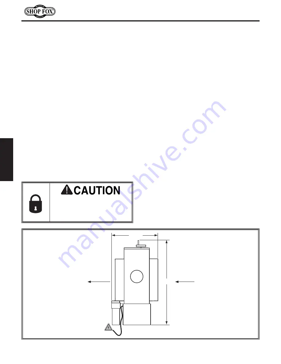
See.below.for.

required.space.allocation.

Physical.Environment

The physical environment where your machine is 

operated is important for safe operation and the 

longevity of its components. For best results, 

operate this machine in a dry environment 

that is free from excessive moisture, hazardous 

chemicals, airborne abrasives, or extreme 

conditions. Extreme conditions for this type 

of machinery are generally those where the 

ambient temperature range exceeds 41°–104°F; 

the relative humidity range exceeds 20–95% 

(non-condensing); or the environment is subject 

to vibration, shocks, or bumps.

Electrical.Installation

Place this machine near an existing power 

source. Make sure all power cords are protected 

from traffic, material handling, moisture, 

chemicals, or other hazards. Make sure to leave 

access to a means of disconnecting the power 

source or engaging a lockout/tagout device.

Lighting

Lighting around the machine must be adequate 

enough that operations can be performed 

safely. Shadows, glare, or strobe effects that 

may distract or impede the operator must be 

eliminated.

Children. or. untrained. people.

may.be.seriously.injured.by.this.

machine..Only.install.in.an.access.

restricted.location.

Figure.3.

 Working clearances.

22

1

2

"

35

1

2

"

(Ensure adequate outfeed distance)

(Ensure adequate infeed distance)

Feed Direction

Feed Direction

Summary of Contents for W1854

Page 1: ... Phone 360 734 3482 Online Technical Support techsupport woodstockint com COPYRIGHT APRIL 2018 BY WOODSTOCK INTERNATIONAL INC WARNING NO PORTION OF THIS MANUAL MAY BE REPRODUCED IN ANY SHAPE OR FORM WITHOUT THE WRITTEN APPROVAL OF WOODSTOCK INTERNATIONAL INC 19084KBJHAB Printed in China ...

Page 2: ...ng grinding tool integrity and the usage of personal protective equipment The manufacturer will not be held liable for injury or property damage from negligence improper training machine modifications or misuse Some dust created by power sanding sawing grinding drilling and other construction activities contains chemicals known to the State of California to cause cancer birth defects or other repr...

Page 3: ... Recommended Adjustments 19 OPERATIONS 20 General 20 Stock Inspection Requirements 21 Setting Depth of Cut 22 Sanding 23 Adjusting Conveyor Feed Rate 23 Sanding Tips 24 Choosing Sandpaper 24 Replacing Sandpaper 25 Changing Sanding Drum Speeds 27 ACCESSORIES 28 Sander Accessories 28 MAINTENANCE 29 General 29 Cleaning Protecting 29 Lubrication 30 Cleaning Sandpaper Belts 31 SERVICE 32 General 32 Rep...

Page 4: ...etup operation maintenance and service of this product We stand behind our machines In the event that questions arise about your machine please contact Woodstock International Technical Support at 360 734 3482 or send e mail to tech support shopfox biz Our knowledgeable staff will help you troubleshoot problems and process warranty claims INTRODUCTION If you need the latest edition of this manual ...

Page 5: ...Height 25 x 33 x 33 in Must Ship Upright Yes Electrical Power Requirement 110V Single Phase 60 Hz Full Load Current Rating 13 92A Minimum Circuit Size 20A Connection Type Cord Plug Power Cord Included Yes Power Cord Length 6 ft Power Cord Gauge 14 AWG Plug Included Yes Included Plug Type 5 15 Switch Type Paddle Safety Switch w Removable Key Motors Conveyor Belt Horsepower 1 8 HP Amps 0 92A Speed 1...

Page 6: ...e Finish Powder Coated Other Related Information Floor To Table Height 35 40 in Sanding Belt Tension Spring Loaded Conveyor Belt Length 45 in Conveyor Belt Width 18 in Belt Roller Size 1 3 8 in Number of Dust Ports 1 Dust Port Size 4 in Other Country of Origin China Warranty 2 Years Approximate Assembly Setup Time 1 1 2 Hours Serial Number Location ID Label ISO 9001 Factory No Certified by a Natio...

Page 7: ...rkload overloads circuit Press button to reset breaker D Table Height Indicator Displays approximate distance between sanding drum and conveyor belt E Dust Port Connects sander to 4 dust collection system F Table Elevation Handwheel Raises and lowers conveyor table G Rotate counterclockwise to lower table rotate clockwise to raise table One full rotation moves the table approximately 0 060 1 16 G ...

Page 8: ...s or alcohol when tired or when distracted ELECTRICAL EQUIPMENT INJURY RISKS You can be shocked burned or killed by touching live electrical components or improperly grounded machinery To reduce this risk only allow an electrician or qualified service personnel to do electrical installation or repair work and always disconnect power before accessing or exposing electrical equipment DISCONNECT POWE...

Page 9: ...uce accidental contact with moving parts or flying debris make sure they are properly installed undamaged and working correctly FORCING MACHINERY Do not force machine It will do the job safer and better at the rate for which it was designed NEVER STAND ON MACHINE Serious injury may occur if machine is tipped or if the cutting tool is unintentionally contacted STABLE MACHINE Unexpected movement dur...

Page 10: ...hen sanding small workpieces and keep hands and fingers at least 2 away from sanding surface WORKPIECE INSPECTION Nails staples knots or other imperfections in workpiece can be dislodged and thrown from sander at a high rate of speed at people or cause damage to sandpaper or sander Never sand stock that has embedded foreign objects or questionable imperfections SANDPAPER DIRECTION Feeding workpiec...

Page 11: ...ts Circuit Type 110V 120V 60 Hz Single Phase Circuit Size 20 Amps Plug Receptacle NEMA 5 15 Full Load Current Rating The full load current rating is the amperage a machine draws at 100 of the rated output power On machines with multiple motors this is the amperage drawn by the largest motor or sum of all motors and electrical devices that might operate at one time during normal operations Full Loa...

Page 12: ...w one Grounding Prong Neutral Hot 5 15 PLUG GROUNDED 5 15 RECEPTACLE 110V Figure 1 NEMA 5 15 plug receptacle DO NOT modify the provided plug or use an adapter if the plug will not fit the receptacle Instead have an electrician install the proper receptacle on a power supply circuit that meets the requirements for this machine Extension Cords We do not recommend using an extension cord with this ma...

Page 13: ...ded Hose Clamps 4 2 Items Needed for Setup The following items are needed but not included to set up your machine SUFFOCATION HAZARD Immediately discard all plastic bags and packing materials to eliminate c h o k i n g s u f f o c a t i o n hazards for children and animals USE helpers or power lifting equipment to lift this machine Otherwise serious personal injury may occur Wear safety glasses du...

Page 14: ...S ARE 1MM APART 5mm 10mm 20mm 15mm 25mm 40mm 30mm 35mm 45mm 50mm 60mm 55mm 70mm 65mm 75mm W A S H ER DIAM E T E R 5 8 W A S H ER DIAM E T E R 9 16 1 2 W A S H ER DIA M E T E R W A S H ER DIA M E T E R 12mm W A S H E R DIA M E T E R 10mm 7 16 W A S H ER DIA M E T E R W A S H E R DIA M E T E R 8mm 3 8 W A S H E R DIA M E T E R 5 16 W A S H E R DIA M E T E R 1 4 W A S H E R DIA M E T E R 10 W A S H E...

Page 15: ...lat Washers 8mm 8 Carriage Bolts M8 1 25 x 15 16 Flange Nuts M8 1 25 16 Combination Wrench 8 12mm 1 Hex Wrenches 4 5 6mm 1 Ea Inventory The following is a list of items shipped with your machine Before beginning setup lay these items out and inventory them Note If you cannot find an item on this list carefully check around inside the machine and packaging materials Often these items get lost in pa...

Page 16: ...tant for safe operation and the longevity of its components For best results operate this machine in a dry environment that is free from excessive moisture hazardous chemicals airborne abrasives or extreme conditions Extreme conditions for this type of machinery are generally those where the ambient temperature range exceeds 41 104 F the relative humidity range exceeds 20 95 non condensing or the ...

Page 17: ...ge bolts and flange nuts as shown in Figure 5 4 Repeat Steps 2 3 with remaining components to build remaining stand leg assembly 5 Mount top and bottom short brackets to stand leg assembly with 2 M8 1 25 x 15 carriage bolts and 2 M8 1 25 flange nuts as shown in Figure 6 Do not final tighten stand bolts until all stand components have been assembled It will help with aligning and leveling stand lat...

Page 18: ...h belt access panel faces pallet Move left bottom edge of sander forward as shown in Figure 8 Note The base should be even with or stick out from the edge of the pallet to properly install stand assembly 12 Secure stand to sander with 4 M8 1 25 x 20 hex bolts 8 8mm flat washers and 4 M8 1 25 hex nuts as shown in Figure 10 13 Lift up on stand and remove blocks 11 Lay stand assembly on blocks as sho...

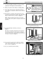
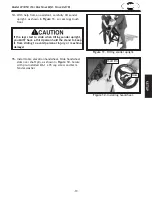
Page 19: ...personal injury or machine damage Figure 11 Tilting sander upright 15 Install table elevation handwheel Slide handwheel slots over shaft pin as shown in Figure 12 Secure with pre installed M6 1 x 35 cap screw and 6mm fender washer 14 With help from an assistant carefully tilt sander upright as shown in Figure 11 so rear legs touch floor Figure 12 Installing handwheel Shaft Pin Slots ...

Page 20: ...t collection system we recommend using a system that can collect a minimum of 400 CFM AT THE DUST PORT When the dust collection is working properly a fine layer of dust may be present on your stock as it comes out of the sander This is a normal characteristic of all drum sanders Items Needed Qty Dust Collection System 1 Dust Hose 4 1 Hose Clamps 4 2 To connect dust port to a dust collector do thes...

Page 21: ...s up and runs correctly and 2 the safety disabling mechanism on the switch works correctly To test run the machine do these steps 1 Clear all setup tools away from machine 2 Connect machine to power supply 3 Turn machine ON verify motor operation then turn machine OFF The motor should run smoothly and without unusual noises 4 Remove switch disabling key see Figure 14 5 Try to start machine with pa...

Page 22: ...cal sanding operation the operator does the following 1 Examines workpiece to verify it is suitable for sanding and to determine which sanding belt grit size to use 2 Installs and tensions sanding belt 3 Verifies workpiece will have necessary outfeed clearance and support If workpiece is wider than conveyor table operator supports workpiece full width 4 Adjusts table height to approximate workpiec...

Page 23: ... by all types of sanding operations even if a dust collector is used Additionally the life of the machine and sanding belts will be greatly reduced or immediately damaged from sanding improper materials or from exposure to the fine dust created when doing so Foreign Objects Nails staples dirt rocks and other foreign objects are often embedded in wood While sanding these objects can become dislodge...

Page 24: ...s well below sanding drum then raise table allowing a gap between workpiece and sanding drum Note When adjusting table to sand a thicker workpiece lower and then raise table to remove backlash from adjustment mechanism 2 Turn machine ON and feed workpiece into sander SLOWLY raise conveyor table until workpiece makes light contact with sanding drum This is the correct height to begin sanding workpi...

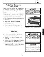
Page 25: ...nveyor motor is OFF Damage to the V belt and the adjusting mechanism can result Figure 16 Location of conveyor feed rate dial Overloading the motor or pushing the sander to failure weakens the electrical system Repeatedly doing so is abuse to the machine that will cause motor capacitor or thermal breaker damage which is not covered by the warranty DO NOT sand more than one board at a time Minor va...

Page 26: ...hickness Reduce snipe when sanding more than one board of the same thickness by feeding them into the sander with the front end of the second board touching the back end of the first board Feed boards into the sander at different places on the conveyor to maximize sandpaper life and prevent uneven conveyor belt wear DO NOT sand boards less than 6 long or less than 1 8 thick to prevent damage to th...

Page 27: ...s easier than using the drawing shown in Figure 18 5 Loosen cap screw on left clamp and fully remove sandpaper strip 6 Use old sandpaper strip as a pattern if at all possible Otherwise use pattern in Figure 18 to cut a new piece of sandpaper to the necessary shape After cutting the 121 2 angled sides measure 2 along same sides and cut off ends with a knife 7 Insert corner of new sandpaper into lef...

Page 28: ...wrench from access hole Sandpaper should seat flat against roller and not overlap at any point If the sandpaper does not fit into the right clamp you may have inserted sandpaper too deeply into left clamp Also check to make sure the length width and angled cuts match the pattern in Figure 18 on Page 25 Make adjustments to sandpaper if necessary If sandpaper completely covers access hole you may ha...

Page 29: ...n do these steps 1 DISCONNECT MACHINE FROM POWER 2 Remove pulley cover 3 Loosen motor mount cap screws shown in Figure 24 and lift motor pulley to de tension belt 4 Tighten motor mount cap screws to keep motor de tensioned during belt change 5 Roll V belt onto correct pulley for sanding operation and follow steps outlined in Tensioning V Belt on Page 33 to properly tension belt before operation Hi...

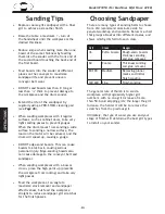
Page 30: ... Oxide Sanding Rolls 3 x 50 D3162 60 Grit Use for thickness sanding and glue removal D3546 80 Grit Use to remove planer marks and initial sanding D3163 100 Grit Use to remove planer marks and initial sanding D3547 120 Grit Use for finish sanding D3164 150 Grit Use for finish sanding D3997 180 Grit Use for finish sanding D3998 220 Grit Use for finish sanding The Shop Fox D3003 PRO STIK Cleaning Pad...

Page 31: ...ine operation if you ever observe any of the items below shut down the machine immediately and fix the problem before continuing operations Loose mounting bolts Damaged sanding belt Worn switch Worn or damaged cords or plugs Damaged V belt Any other unsafe condition Clean vacuum dust buildup from inside cabinet and off of the motor Daily Oil the conveyor belt roller and drive bushings Every 6 Mont...

Page 32: ...nks and screw threads Clean the helical gear see Figure 27 and place a dab of grease on the teeth Move the table up and down to spread the grease thoroughly throughout the mechanism Lubrication The feed belt bushings should be lubricated daily with ISO 32 Multi Function Machine Oil The bearings do not need lubrication Avoid using excess lubrication Too much lubricant attracts sawdust and will clog...

Page 33: ...heavy loading of material Use a Shop Fox Model D3003 PRO STIK Cleaning Pad as shown in Figure 28 To clean sandpaper belt do these steps 1 DISCONNECT MACHINE FROM POWER 2 Set table to thickness of cleaning pad 3 Connect machine to power then run pad through sander two or three times DO NOT take too deep of a cut the belt should barely touch cleaning pad Figure 28 D3003 PRO STIK Cleaning Pad ...

Page 34: ...during belt change 5 Roll V belt off both pulleys and install new V belt on pulley grooves for desired speed setting see Changing Sanding Drum Speeds on Page 27 6 Properly tension V belt refer to Tensioning V Belt on Page 33 for more information 7 Re install pulley belt access cover from Step 2 Replacing V Belt MAKE SURE that your machine is unplugged during all service proce dures If this warning...

Page 35: ...ter mod erate use Check frequently after installation and re tension if necessary To adjust V belt tension do these steps 1 DISCONNECT MACHINE FROM POWER 2 Open belt access panel 3 Check tension of V belt then adjust tension by loosening motor mount cap screws see Figure 31 4 Tension V belt by pushing down on bottom motor pulley with one hand then tighten motor mount cap screws and check belt tens...

Page 36: ...ight down outside face of pulleys to see if sanding drum and motor pulleys are parallel and aligned with each other see Figure 32 If pulleys are aligned go to Step 7 If pulleys are not aligned perform Steps 4 6 4 Remove V belt see Replacing V Belt on Page 32 5 Loosen set screws on motor pulley and sanding drum pulley then align both pulleys see Figure 33 6 Tighten set screws replace V belt and rep...

Page 37: ...elt tracking do these steps 1 Turn machine ON and watch conveyor belt track If the belt tracks evenly leave it alone If the belt quickly moves to one side immediately turn the machine OFF and adjust the belt tracking before running the conveyor again Proceed to Step 2 2 Loosen lock nut see Figure 34 on side that conveyor belt tracks towards and tension tracking adjustment screw until conveyor belt...

Page 38: ...nuts and turn both conveyor belt tensioning bolts clockwise one full turn at a time until conveyor belt no longer slips during operation If conveyor belt starts tracking to one side back off the conveyor belt tensioning bolt that is being adjusted If conveyor belt continues tracking to one side immediately turn machine OFF and follow Tracking Conveyor Belt instructions on Page 35 5 Tighten lock nu...

Page 39: ...elease tension from conveyor belt 4 Remove outside table cap screws shown in Figure 37 and loosen corresponding cap screws on inside edge 5 Have assistant lift outside edge of table then slide conveyor belt off 6 Clean any dirt or dust off table and rollers have assistant lift table then slide new conveyor belt on 7 Re install and tighten all table cap screws 8 Tighten conveyor belt adjustment bol...

Page 40: ... as shown in Figure 38 Making Gauge Blocks Figure 38 Edge jointing on a jointer 15 30 45 Previously Jointed Edge Opposite Edge Rip Cut with Table Saw Figure 39 Rip cutting on a table saw 2 Place jointed edge of 2x4 against table saw fence and rip cut just enough off opposite side to square up two edges of the 2x4 as shown in Figure 39 3 Cut 2x4 into two even pieces to make two 36 long wood gauge b...

Page 41: ...deration or in other words wait until the chain starts moving before starting to count handwheel rotation 5 Starting at one end find thickest feeler gauge that can pass between drum and your gauge block The feeler gauge should slide with moderate resistance without forcing drum to roll 6 Repeat Step 5 at other end of the drum If the difference between the two sizes is 0 002 or less then no adjustm...

Page 42: ... rollers do these steps 1 DISCONNECT MACHINE FROM POWER 2 Place gauge blocks on feed belt as shown in Figure 43 3 Raise table until blocks just touch the rear pressure roller 4 Find the largest size feeler gauge that can pass between sanding drum and your gauge block The feeler gauge should slide with moderate resistance without forcing drum to roll If gap is 0 004 0 1mm or less then no adjustment...

Page 43: ...ler do these steps 1 DISCONNECT MACHINE FROM POWER 2 Loosen hex nut securing adjustment cap screws on both ends of rear pressure roller shown in Figure 45 3 Rotate cap screw clockwise to raise pressure roller or counterclockwise loosen cap screw to lower pressure roller 4 Adjust rear pressure roller until it is equal to or up to 0 004 0 1mm lower than height of the drum Figure 44 Rear pressure rol...

Page 44: ...ntrifugal switch contact points at fault 9 Motor bearings at fault 10 Motor at fault 1 Only sand wood or wood products ensure moisture is below 20 2 Reduce sanding depth 3 Decrease feed rate sanding speed Page 27 4 Clean replace sandpaper Page 31 reduce feed rate Page 23 or sanding depth Page 22 5 Inspect tension replace V belt align pulleys Pages 32 33 34 6 Clean motor let cool and reduce workloa...

Page 45: ...ift screws are dirty or loaded with sawdust 3 Chain idler sprocket cap screws overtightened 4 Elevation handwheel helical gear is dirty or loaded with sawdust 1 Loosen elevation lock knob 2 Clean and re grease table lift screws Page 30 3 Adjust cap screws on idler sprocket so it can spin freely 4 Clean and re grease the helical gear Page 30 Burn marks on workpiece 1 Using too fine of sanding grit ...

Page 46: ... but it may not match your machine Always use the wiring diagram inside the motor junction box CAPACITORS INVERTERS Some capacitors and power inverters store an electrical charge for up to 10 minutes after being disconnected from the power source To reduce the risk of being shocked wait at least this long before working on capacitors CIRCUIT REQUIREMENTS You MUST follow the requirements at the beg...

Page 47: ...le Speed Dial Feed Belt Motor 90W 110V DC LINE LOAD Main Motor 1 5HP 110V 1 PH Motor Junction Box Machine Cabinet Run Capacitor 25uF 250V Start Capacitor 350uF 125V ACL ACN Doout Doout 3 6 1 4 STOP Read Page 44 Before Wiring Wiring Diagram This motor wiring diagram is current at the time of printing however always use the diagram on the inside of the junction box cover when rewiring your motor ...

Page 48: ...35 57 99 51 35 60 119 124 134 131 132 126 134 132 131 138 141 124 139 135 99 51 60 40 100 37 54 123 15 92 108 16 72 23 120 121 93 6 9 1 4 5 2 3 7 8 10 11 12 13 14 117 80 99 60 140 130 133 27 137 123 25 28 24 31 32 2 112 29 25 99 99 136 53 142 33 22 30 34 118 2 89 90 26 2 26 3 5 42 1 143 144 145 146 ...

Page 49: ... 64 116 63 85 79 55 113 114 35 69 51 35 99 51 61 62 63 64 78 118 87 82 84 84 75 60 37 89 57 59 122 127 128 98 71 49 43 44 45 47 68 46 74 5 76 3 2 50 52 57 58 100 87 2 3 83 86 88 70 67 96 92 70 57 60 99 19 48 2 3 97 44 93 80 2 3 91 90 81 5 73 109 110 111 74 1 74 2 74 3 74 4 74 5 74 6 74 7 74 8 Main Breakdown Cont ...

Page 50: ...3 X1854023 TABLE HEIGHT SCALE 64 X1854064 ELEVATION SCREW CAP 24 X1854024 CAP SCREW M6 1 X 12 65 X1854065 GEAR 65T 25 X1854025 TORSION SPRING LT 66 X1854066 BRACKET 26 X1854026 TORSION SPRING RT 67 X1854067 ELEVATION SCREW ROD 27 X1854027 ROLLER MOUTING PLATE 68 X1854068 LOWER CASTING 28 X1854028 ROLLER 69 X1854069 V BELT B40 29 X1854029 PIVOT SHOULDER PIN 70 X1854070 CAP SCREW M8 1 25 X 12 30 X18...

Page 51: ...128 X1854128 SHOULDER SCR M8 1 25 X 13 9 X 115 94 X1854094 SANDING BELT 100 GRIT 3 X 84 129 X1854129 BELT DRUM 95 X1854095 CONVEYOR BELT 130 X1854130 CONNECTION WIRE 2 14AWG 100L 96 X1854096 CAP SCREW M6 1 X 30 131 X1854131 BELT LOCKING BLOCK 97 X1854097 POWER CORD 14G 3W 72 5 15P 132 X1854132 COMPRESSION SPRING 98 X1854098 FLAT WASHER 12MM 133 X1854133 CONNECTION WIRE 1 14AWG 100L 99 X1854099 FLA...

Page 52: ...12 Do not expose to rain or use in wet locations 13 Do not operate under influence of drugs or alcohol or if tired 14 Prevent unauthorized use by children or untrained users restrict access or disable machine when unattended WARNING ENTANGLEMENT HAZARD Tie back long hair and roll up sleeves before using this machine WARNING EYE LUNG INJURY HAZARD Always wear safety glasses and a respirator when us...

Page 53: ...Model W1854 For Machines Mfd Since 02 18 ...

Page 54: ...tape along edges please do not staple Fold along dotted lIne Fold along dotted lIne Woodstock international inc p o box 2309 bellingham Wa 98227 2309 place stamp Here ...

Page 55: ...the scope of Woodstock International Inc s warranty then the original owner must bear the cost of storing and returning the product This is Woodstock International Inc s sole written warranty and any and all warranties that may be implied by law including any merchantability or fitness for any particular purpose are hereby limited to the duration of this written warranty We do not warrant that Sho...

Page 56: ......
Reviews: