Automatic Tool Changer (ATC) Installation Manual • December 1, 2016
© Copyright 2016 ShopBot Tools, Inc.
page 14
Route the other end of the 3/8” tubing through the X-axis E-chain,
Y-axis E-chain, and up to the YZ car. Route the 3/8” tubing to the
back right side of the spindle (as if facing the spindle). Connect the
tubing into the open push-in connection tee.
Move the Z-axis as close to
the table surface as possi-
ble to make sure that Z-axis
travel is not shortened due
to hose length.
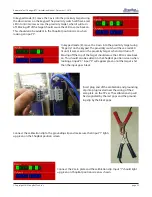
Route ¼” and 5/32” tubing
from the output of the pre-
cision regulator (see left) to
the base of the large, verti-
cal air cylinder on the front
of the YZ car (see right).
Trim tubing to proper length
and push it into the connectors.
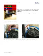
Connect two pieces of 1/4” tubing to the top two push-in
connectors on the manifold.
Route the other end of the tubing to the front side of the
spindle. Trim tubing to length.
Connect the 1/4” tubing from the top manifold connection to
left connection in front of the spindle (identified as 6-7 bar).
Connect the 1/4” tubing from the second manifold connec-
tion to right connection in front of the spindle (identified as 4
bar).


