Automatic Tool Changer (ATC) Installation Manual • December 1, 2016
© Copyright 2016 ShopBot Tools, Inc.
page 16
ATC Installation (Electrical)
This portion of the installation will cover the electrical system, wire routing, and the hook-up requirements.
Emergency Stop Switch and Three-Button Pendant Install
The three-button pendant and the separate emergency stop are bundled together for shipping. Both must be
attached for either one to function.
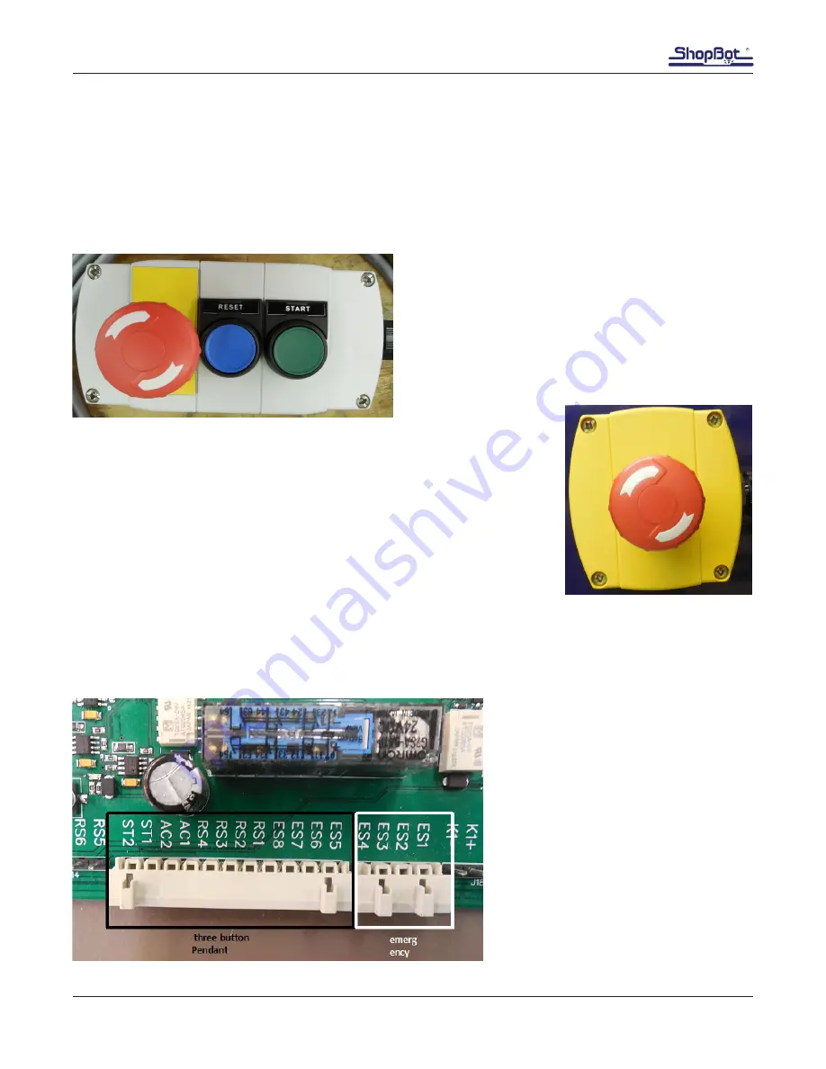
The ShopBot three button pendant allows the operator
to locate the reset, start, and extra emergency stop but-
tons in a convenient location away from the control box.
Control boxes may differ slightly from pictures shown,
depending on which model is present.
The separate emergen-
cy stop switch also comes fitted with a Wago connector that plugs into the
control board. Power for the router or spindle is routed through the control
box safety controls so that activating the emergency stop, by hitting the red
“STOP” button, will stop the movement of the carriages and power down the
router or spindle. This stop button should be mounted to the gantry in an
easy-to-access location. There are pre-drilled holes on the top of each end
plate for easy attachment.
Note: Input #4 will flash red on the computer screen and the ShopBot control
software will not allow the ShopBot to move if the emergency stop is not
connected.
Wire Emergency Stop and Three-Button Pendant
Run cables from the three-button pen-
dant and the separate emergency stop
switch into the control box through the
Roxtec opening.
Plug in the longer Wago connector (for
the three-button pendant) into its corre-
sponding female plug on the board. Plug
in the smaller connector (for the emer-
gency stop) into the female connector
beside the longer one.


