power supply fan running. Turn on the STEPPER switch and you should
hear the steppers jump to locked position. You should not be able to turn
the handles at this point. The DRO display may or may not light up at this
point. It is hard wired into the power switch, but also has a separate ON-
OFF switch on the back of the display. On the lower left of the Mach 3
screen you will see a reset button flashing- click on this to reset. Note- every
time you turn off the stepper switch, the reset will flash and you will need to
reset it. Once the reset button is reset, go to the top of the screen and select
MDI (Manual Data Input). A bar will open up for data entry. First type
G91 and hit enter. G91 is the code for incremental moves. Now type G0 Z1
and hit enter. The carriage should move up 1” to the right. Now try G0 Z-1
and hit enter. The carriage should move 1” to the left. Try the same
commands for X axis according to the chart on the right sheet metal shield.
When testing any axis, if you hear a whining noise and there is no motion,
don’t worry- that is just the stepper stalling and it won’t hurt anything.
Contact us for help with diagnosing the problem.
PLEASE NOTE: The command is G “ZERO” not G “OH”
Now try a spindle command- type M3 S200 and hit enter. The lathe spindle
should turn at 200 RPM. Type M5 and enter to stop the spindle. Type M4
S200 and the spindle should rotate the opposite direction. Always use M5 to
stop the spindle.
If the carriages or spindle move the wrong direction go to the bottom of this
file for instructions.
As your spindle is running, on the Mach 3 screen you will have a display that
shows the RPM you requested and another display showing the true rpm as
read from the spindle sensor. These should be very close, but can be
adjusted in the CONFIG files. At this point you are ready to begin the final
adjustments of the spindle rpm, steps per inch and backlash compensation.
We have included a number of files for these operations on our website. We
have set the adjustments as close as possible, but every machine will be
slightly different and once installed in its final location these fine
adjustments must be completed by the operator. The functions of each of
the VFD codes are set forth in the V-8 VFD manual which we have on our
website. Following are a few of the more common adjustments used in daily
operations.
Codes P0-02 and P0-03 and P0-11 allow you to change from Mach 3 control
of your spindles to manual control according to the settings on the decal.
Codes P0-08 and P0-10 are the Hz settings which control your maximum
spindle speeds. Please note, when adjusting these settings, the 2 code settings
must always match. The factory default setting is the maximum allowable of
120.
Summary of Contents for MILL TURN
Page 12: ......
Page 13: ......
Page 14: ......
Page 15: ...5C COLLET SET 4 JAW CHUCK ...
Page 16: ...FOLLOW REST ...
Page 17: ...STEADY REST ...
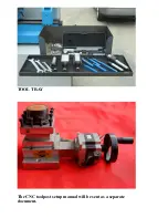
Page 18: ...TOOL TRAY The CNC toolpost setup manual will be sent as a separate document ...


