CABLE CONNECTIONS FOR STEPPERS
AND DRO
To prevent any damage to the cables and the Gecko drive, and due to
the position of the DRO display in shipping, the cables are left
unconnected but are labelled for proper connection to the machine.
All cables must be securely attached with the holding screws, because a
loose connection can cause Mach 3 to fault out during a program.
CAUTION- Always turn off the CNC Power
switch before disconnecting a cable.
DRO CABLES
The DRO has 2 modes for lathe and mill, but when first powered up it
should go into the default Mill mode. So just plug the cables into the
display and then watch which display is reading when you move the X
axis and move that cable to the X axis port on the display. The same
procedure for Z. The CNC toolpost will attach to the A axis. You can
swap DRO cables with power on with no problem. Once the cables are
in their proper positions, secure them with the screws.
TEST RUN THE MACHINE
To begin the first test run of the machine, move the Z and X carriages to
their mid travel points, this will give you plenty of clearance for your first
moves. Bring the computer mount around and adjust it to a comfortable
position. Hook up the keyboard and mouse and the monitor and Parallel
port cables. Plug the PC power cable in to the 220 volt wall outlet. Turn the
PC on. It should boot up and on your desktop screen you should have
several icons. RECYCLE BIN, MACH LOADER. Double click Mach
Loader and then select LATHE. If you have some extra selections in the
Mach loader, such as Plasma, Mach3Turn and Mach3Mill, just delete them,
as they are default XML files from the Mach 3 installation and do not have
the correct settings for your machine. Also, delete any extra icons from the
Desktop for Mill, Turn or Plasma and just use the Mach Loader. The Mach
3 screen should load up at this point. Now make sure all your switches on
the machine panel are in the OFF position and plug your 220 cord into the
220 outlet. Be sure your E-Stop switch is engaged by twisting it. Set the
selector switch to LATHE mode and turn on the SPINDLE POWER switch.
You should get a red light and hear the auxiliary cooling fan running. Turn
on the CNC POWER switch and you should get a red light and also hear the
Summary of Contents for MILL TURN
Page 12: ......
Page 13: ......
Page 14: ......
Page 15: ...5C COLLET SET 4 JAW CHUCK ...
Page 16: ...FOLLOW REST ...
Page 17: ...STEADY REST ...
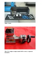
Page 18: ...TOOL TRAY The CNC toolpost setup manual will be sent as a separate document ...


