ADM-880C 07/20/09
55
14.0 METER ACCURACY FIELD TESTING
14.1 METER ZERO FUNCTION
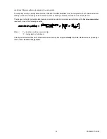
Disconnect all tubing from the positive (+) and negative (-) ports of the meter. Perform several readings with the meter set
for the flow or velocity mode, with
no air
passing across the meter ports. The meter should display zero readings, but may
occasionally show a low reading such as 25 cfm or fpm. An
occasional
positive or negative reading is random electronic
"noise" and may be disregarded.
If the zero test readings tend to be either positive or negative and greater than 25 cfm, the zero bias indicated will affect the
accuracy of low air flow or velocity measurements. Check for any obstruction of the meter connections and clean if needed.
Be sure that there is no moisture or condensation in the meter or meter connections. If the meter has been exposed to water
or high humidity, followed by rapid cooling, water may have condensed inside the meter. In this event, the meter should be
placed in a warm dry atmosphere (between 80
/
F and 130
/
F) for 24 hours. Afterward, the batteries will need to be recharged
for 10 hours at a temperature less than 113
/
F. If a zero bias or other problem persists, call the factory for advice.
14.2 DIFFERENTIAL PRESSURE FUNCTION
Check the DIFF PRES function zero accuracy by taking a reading with both meter ports open to the atmosphere. Be sure
the ports are
not
exposed to a draft. The reading should be 0.0000 in wc ± 0.0001 in wc.
Check the differential pressure reading accuracy by measuring a static pressure source at approximately the following
pressures: 0.1250 in wc; 2.000 in wc; 30.00 in wc. Confirm the pressure readings by comparison with an appropriately
accurate inclined manometer at the 0.1250 and 2.000 in wc differential. The 30.00 in wc differential may be checked using
a U-tube and water.
Since the AirData Multimeter passes a very small sample of the air through the meter during each measurement (see
SPECIFICATIONS), it should be connected to the pressure source independently of any other meter, manometer, or U-tube.
To avoid pulsation or "cross talk" through the pressure source tubing, use shutoff valves to isolate the AirData Multimeter
and the reference pressure gage. The pressure source must be self-replenishing, such as a pressure drop across a needle
valve, orifice, or orifice plate.
14.3 ABSOLUTE PRESSURE FUNCTION
You may confirm the accuracy of the absolute pressure correction by taking a reading with the meter ports open to the
atmosphere and comparing the reading with the actual barometric pressure. The reading should be within ± 2%
(approximately .5 in Hg) of the actual barometric pressure to maintain the specified accuracy for velocity and air flow density
correction.
CAUTION: Testing of absolute pressures greater or less than local barometric pressure must be performed with the
reference pressure applied to the positive (+) and the negative (-) ports at the same time. This precaution avoids excessive
pressure input to the differential pressure transducer.
NOTE: Weather service or airport reports of barometric pressure have usually been adjusted for altitude, so the pressure
can be used for altimeter adjustment. The barometric pressure announced on television or radio stations is generally
obtained from weather service reports. This altitude corrected barometric pressure must
not
be used in density correction
equations for comparison with a FlowHood. An estimation of the actual barometric pressure may be obtained by deducting
approximately 1.0 in Hg for each 1000 feet above sea level.
14.4 AIR FLOW ACCURACY
Air flow accuracy is confirmed by comparing a very careful pitot tube traverse with the results obtained using the FlowHood.
An accurate inclined manometer, micromanometer, or AirData Multimeter may be used for the duct traverse. An inclined
manometer used for the duct traverse should have minor scale divisions of .005 in wc or less, and should have direct velocity
markings down to at least 400 fpm. The accuracy of the comparison tests will depend on both the accuracy of the velocity
traverse, and the accuracy of the air flow calculations.
A multipoint pitot tube traverse is performed on a supply duct which serves a single supply diffuser. The pitot tube should
be a type approved by the NPL (National Physics Laboratory, U.K.) or AMCA (Air Moving and Conditioning Association, U.S.).
The duct velocity should be at least 800 fpm; the duct should be properly sealed and taped; and the connection to the diffuser
should be airtight. The duct traverse location should have straight duct for six to eight duct diameters upstream, and three
to four diameters downstream. For example, a one foot diameter duct requires eight feet of straight duct upstream and four
feet downstream.
Summary of Contents for AIRDATA ADM-880C
Page 42: ...ADM 880C 07 20 09 37 FIGURE 6 3 VELGRID ASSEMBLY...
Page 50: ...ADM 880C 07 20 09 45 FIGURE 10 1 FRAME STORAGE FIGURE 10 2 FLOWHOOD IN CASE...
Page 51: ...ADM 880C 07 20 09 46 FIGURE 10 3 FLOWHOOD ASSEMBLY...
Page 53: ...ADM 880C 07 20 09 48 FIGURE 10 7 1X5 FRAME ASSEMBLY FIGURE 10 8 3X3 FRAME ASSEMBLY...


