background image

Operating Instructions: 


Following is a brief description of the various switches and dials: 
 

1.


POWER:   

Flip POWER switch ON to energize control box.   

Red POWER light will illuminate.  The unit requires 5 seconds to 
initialize.  Avoid pressing any control buttons while unit initializes. 


2.


MANUAL:

    Operate control box left, right, and change speeds. 


3.


LOGIC:  


Switch reverses the direction that the cow or flag 

travels.


Example:  

After the Pro Cutter is installed, attach remote control to 

your  wrist  (wrist  watch  position)  and  button  assembly  on  index 
finger.  Press left switch with your thumb.  If cow or flag travels to 
left,  you’re  ready  to  go.    However,  if  cow  or  flag  travels  right 
toggle LOGIC switch.  This will cause the cow or flag to travel left 
as you press left switch – and right as you press right switch. 
 

4.


FUSE:   

Power  surges,  faulty  cord,  or  defective  component  may 

cause a fuse to blow.  When this happens, remove fuse and replace 
using  only  4  amp/250v  AGC  fuse,  or  permanent  damage  may 
result.   

NOTE:  power indicator light will not illuminate when fuse is bad. 


5.


SPEED DIALS:  Front face of control box 


SPEED 1:  

The left speed dial is the starting speed.  When the 

control  box  is  asked  to  run  using  either  remote  or  manual 
control switches, the cow or flag will begin moving at Speed 1 
regardless  of  direction.    To  stop,  simply  release  button  or 
switch.


SPEED  2:   

The  right  speed  dial  is  second  speed.    To  access 

Speed  2,  begin  by  pressing  a  run  button  on  remote  or  manual 
control.  The cow or flag will begin moving at Speed 1.  When 
traveling  at  Speed  1,  release  button  and  re-press  immediately.  
Control box will shift to Speed 2.  


EXAMPLE:

    Set  Speed  1  (left  dial)  to  "15",  and  Speed  2  to 

"45".  When a run button is pressed, the cow or flag will move 
at  SPEED  1.    To  shift  to  SPEED  2,  start  the  cow  moving  at 

Summary of Contents for PRO CUTTER 1502

Page 1: ...rovide years of trouble free service Pro Cutter 1502 with Performance Package Upgrade Packing List control box steel box containing electronic components digital remote control w Stepper Technology of...

Page 2: ...wo snaps supports the cow s head and the slide tube with one snap slides freely on back part of loop supports the cow s shoulder 4 Install TECH line The tech line is static and supports the cow s hip...

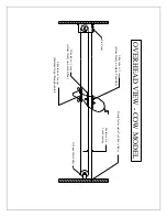
Page 3: ...Off side Idler Pulley OVERHEAD VIEW COW MODEL Firmly fasten static Tech line to fence slides freely on static Tech line fastened rope through center Slide tube w 2 snaps slides freely on second line...

Page 4: ......

Page 5: ...round off side pulley across arena around pulleys on bottom of control box and back to center Tie one end of rope to left side of flag and other end to right side of flag while removing slack Cut extr...

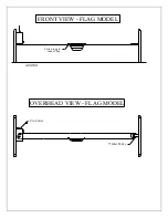
Page 6: ...FRONT VIEW FLAG MODEL GROUND ends of flag Fasten rope to OVERHEAD VIEW FLAG MODEL Pro Cutter 5 Idler Pulley...

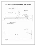
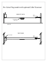
Page 7: ...FRONT VIEW TOP VIEW Pro Cutter Flag models with optional Cable Tensioner GROUND Pro Cutter Fasten rope to ends of flag Cable Tensioner Cable Tensioner...

Page 8: ......

Page 9: ...ght switch 4 FUSE Power surges faulty cord or defective component may cause a fuse to blow When this happens remove fuse and replace using only 4 amp 250v AGC fuse or permanent damage may result NOTE...

Page 10: ...ch remote control to your wrist by inserting your hand through Velcro loop on pouch Attach switch plate to index finger and rotate buttons so they can be pushed by your thumb Walk to center of arena a...

Page 11: ...utter CONTROL BOX will reset the STEPPER back to a 0 setting REMOTE CONTROL The remote control includes an easily replaceable 9 volt alkaline battery and is ready to operate once your Pro Cutter is in...

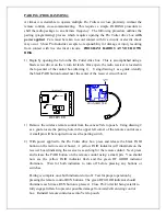
Page 12: ...RNGE PAIRING ANT RESET RECEIVER HOLE PAIRING BATTERY RESET TRANSMITTER 1 Remove the wireless remote control from the canvas Velcro pouch Using drawing 2 as a guide locate the pairing hole in the upper...

Page 13: ...5 Use Pro Cutter only as intended and described in literature 6 Always unplug Pro Cutter when through working each day 7 Do not allow flag to run into ends or damage may occur to electronics rope or b...

Page 14: ...m the date of original purchase During the warranty period Show Pro Industries will repair or at its option replace without charge any SPI product excluding normal wear items providing it is returned...

Reviews: