background image

3

P

P

P

P

P

P

P

P

STEP 2

STEP 3

Issue 1 - 07/11

STEP 4

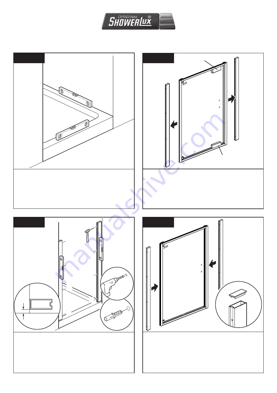
Do not remove the packing blocks on the unit until step 8, 
doing so may result in damage to the product.
Remove the wall channels from the door and put to one side.

Note:- 

Use the opened out enclosure packaging to protect 

your tray/floor & wall while assembling.

Before installation choose which side you want to open the unit from. The current illustrations show a left hand installation 
with the door opening from right to left. Should you require a right hand installation, rotate the unit from top to bottom for the 
opposite configuration to the one shown. 

STEP 1

Check that the tray is level in all directions as shown above.

O

Ø 8mm

fig.1

fig.2

Position the wall channels 10mm from front edge of the tray using the 
measuring tool (

W

). Holding the wall channels to the wall and ensuring 

they are perfectly vertical and parallel to each other, mark off drill hole 
positions onto the tiles using centre punch (

P

). 

Note:

 failing to postion the wall channels as described above will 

reduce the action and performance of the door.
Drill 8mm dia. holes to a depth of 50mm (

fig.1

). Push-fit wall plugs (

O

in beyond depth of tile (

fig.2

). 

Important: Do not fix the wall channels 

to the wall yet.

*

S

Fit the wall channel caps (

S

) to the top of the wall channels 

with the end tab (

*

) in the position shown. 

Note:

 Tapping in 

place with a rubber mallet may help.
Insert the wall channels into the sides of the enclosure.

10mm

Packing Block

Packing 
Block

Summary of Contents for LINEA GLIDE

Page 1: ...ent and product development Duscholux reserves the right to amend specification without notice Showerlux Spares Shop Showerlux Spares Shop Showerlux Product made by The Duscholux Group Showerlux Produ...

Page 2: ...pt for damage that may have been caused in transit Please examine all exposed glass edges and corners prior to assembly damaged edges can cause spontanious breakage during product life time Damage rep...

Page 3: ...otect your floor and wall while assembling CARE MAINTENANCE To prevent the formation of water spots on the glass use the squeegee supplied in the installation fixing pack to wipe down the glass after...

Page 4: ...3 1 SEALS 60140 9 5mm Screw x 8 L 60005 13mm Screw x 2 M 62064 65mm Screw x 8 N 25006 Wall plug x 8 O 62092 Centre punch x 1 P 62072 2 8mm Drill bit x 1 Q 20795 Screw cover x 8 R Frame cap x 1 1 S T J...

Page 5: ...is level in all directions as shown above O 8mm fig 1 fig 2 Position the wall channels 10mm from front edge of the tray using the measuring tool W Holding the wall channels to the wall and ensuring t...

Page 6: ...that the main seal flipper is making full contact with the glass edge see illustrations above From inside the enclosure drill through the eight holes in the side profiles as shown into the wall channe...

Page 7: ...11 Remove packing blocks shown in step 2 Measure between the frame and the pivot block then with the drip deflector Z5 cut a short piece from it to the same length as that measured Fit this short piec...

Page 8: ...vertical profiles of the frame STEP 12 Inside 10cm From outside the enclosure silicone along the bottom of the enclosure on the shower tray all the way around and 10cm up each wall Also silicone 10cm...

Page 9: ...2138 Pivot Block Assembly 60005 60042 2210 2207 2543 2292 2361 60042 2208 2211 2543 2292 60005 60042 2210 2207 2212 60042 2208 2361 2138 Handle Assembly see separate diagrams 2138 LInea Touch Pivot D...

Page 10: ...Issue 1 07 11 Linea Touch Handle Assembly 24828 201748 201744 62059 311215 601221 251127...

Page 11: ...Issue 1 07 11 Glide Handle Assembly DS 2 123 03012 03014 03012 03014...

Page 12: ...10 Issue 1 07 11 This page is intentionally blank...

Reviews: