background image


Order code: 75132 

Multigrip Clamp 

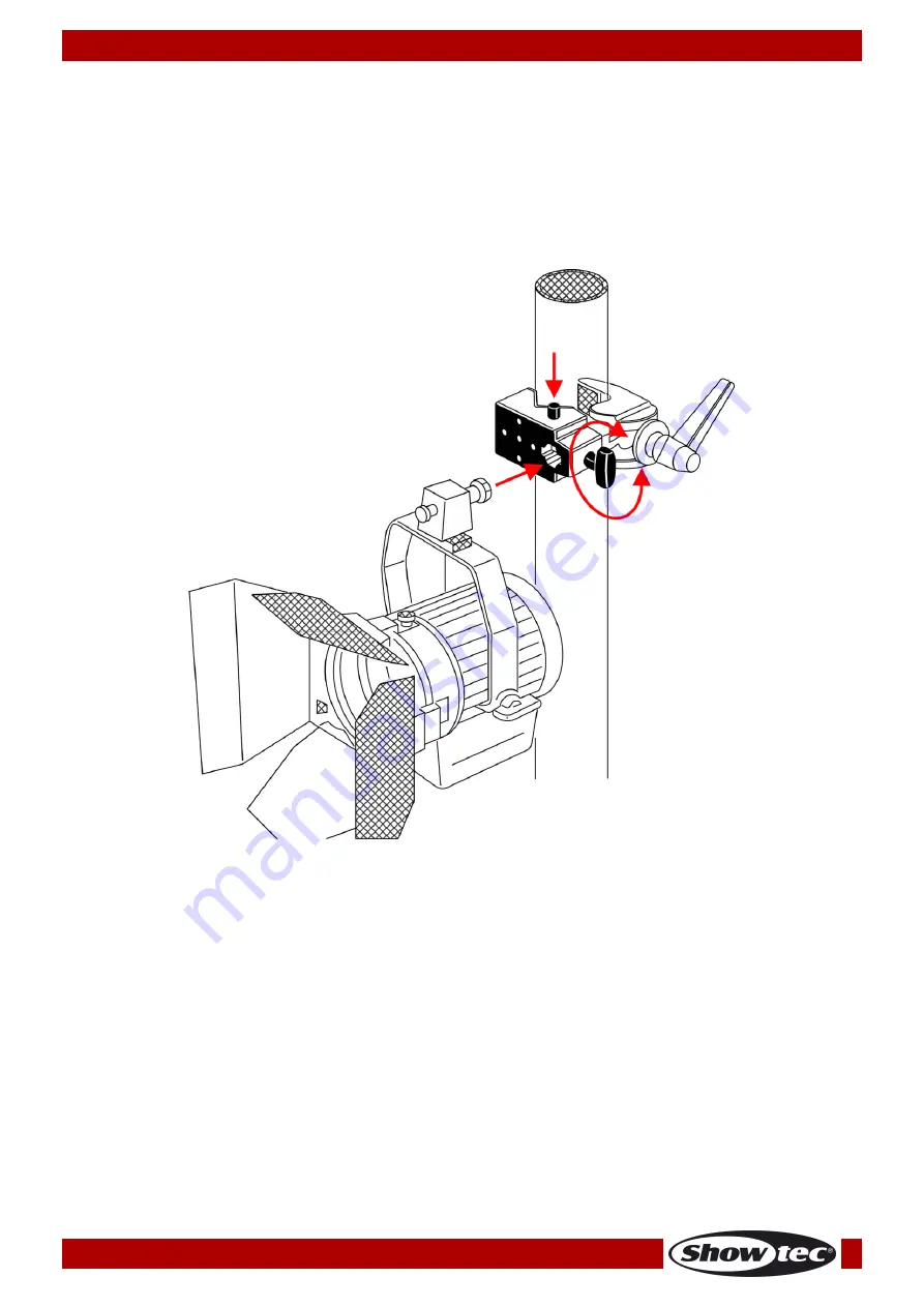
Installing the Multigrip Clamp with the Spigots 

It is possible to install loads by means of the optional spigots: 75133 – Spigot for Multigrip Clamp (M10 x 
25 mm) or 75134 – Spigot for Multigrip Clamp (3/8“–16). 
 
01)


Turn the spigot mounting screw (05) counterclockwise, to loosen it. Otherwise, it might not be 
possible to fully insert the spigot.
 

02)


Press and hold down the safety pin (06) and insert the spigot into the hexagon socket (07)

03)


Release the safety pin (06), to fit the spigot in position. 

04)


Turn the spigot mounting screw (05) clockwise, to stabilize the spigot in the socket. 


Fig. 07 


Summary of Contents for 75132

Page 1: ...Multigrip Clamp V1 Highlite International B V Vestastraat 2 6468 EX Kerkrade the Netherlands Order code 75132 MANUAL ENGLISH ...

Page 2: ... 5 Front 5 Bottom 6 Installation 6 Setup and Operation 6 Inspection Before First Use 6 Installing the Multigrip Clamp onto a Tube Truss 7 Installing the Multigrip Clamp onto Flat Surfaces 8 Installing the Multigrip Clamp with the Spigots 9 Connecting Multiple Multigrip Clamps 10 Maintenance 11 Inspection Maintenance Intervals 11 Regular Inspections 11 Product Specifications 12 Notes 13 ...

Page 3: ...nd do not use the device To maintain perfect condition and to ensure a safe operation it is absolutely necessary for the user to follow the safety instructions and warning notes written in this manual Please consider that damages caused by manual modifications to the device are not subject to warranty This device contains no user serviceable parts Refer servicing to qualified technicians only IMPO...

Page 4: ...ating of the clamp The manufacturer will not accept liability for damages caused by the misuse or incorrect installation of this device Applications that are not described in this manual are not allowed Installation repairs and servicing must be carried out by a qualified technician WARRANTY Till one year after date of purchase Operating Determinations This device is not designed for permanent ope...

Page 5: ...number 04 A brief description of the symptoms Claims The client has the obligation to check the delivered goods immediately upon delivery for any short comings and or visible defects or perform this check after our announcement that the goods are at their disposal Damage incurred in shipping is the responsibility of the shipper therefore the damage must be reported to the carrier upon receipt of m...

Page 6: ...el Maximum load capacity SWL 25 kg Tube diameter 10 55 mm Material Aluminum stainless steel Fixing 2 x M4 thread 1 x M6 thread 1 x 16 mm 5 8 hexagon socket Color Black Dimensions 135 x 57 x 95 mm LxWxH Weight 0 44 kg Optional accessories 75133 Spigot for Multigrip Clamp M10 x 25 mm 75134 Spigot for Multigrip Clamp 3 8 16 Overview Fig 01 Front Fig 02 01 Mounting screw 02 Top 03 Base 04 Wedge for fl...

Page 7: ...son in order to rule out any damage sustained during transport or storage This should happen at least once a year When installing the Multigrip Clamp the user must make sure that the Multigrip Clamp is operated in a safe way The strength and suitability of the suspension point should be checked in advance CAUTION Before installation operators must be instructed and must fully understand the safe u...

Page 8: ...he Multigrip Clamp onto a Tube Truss 01 Turn the mounting screw 01 counterclockwise to loosen the jaw of the Multigrip Clamp 02 Mount the clamp onto a tube truss 03 Make sure that the tube does not exceed the recommended tube size 10 55 mm 04 Make sure that the Multigrip Clamp entirely encompasses the tube 05 Turn the mounting screw 01 clockwise to tighten the clamp and fit it firmly to the tube t...

Page 9: ...ove it 02 Remove the wedge 04 located under the spigot mounting screw 05 03 Insert the wedge 04 into the mounting holes on the Multigrip Clamp Fig 05 04 Turn the mounting screw 01 counterclockwise to loosen the jaw of the Multigrip Clamp 05 Mount the clamp onto a flat surface 06 Make sure that the surface does not exceed the recommended size 10 55 mm 07 Turn the mounting screw 01 clockwise to tigh...

Page 10: ...Spigot for Multigrip Clamp 3 8 16 01 Turn the spigot mounting screw 05 counterclockwise to loosen it Otherwise it might not be possible to fully insert the spigot 02 Press and hold down the safety pin 06 and insert the spigot into the hexagon socket 07 03 Release the safety pin 06 to fit the spigot in position 04 Turn the spigot mounting screw 05 clockwise to stabilize the spigot in the socket Fig...

Page 11: ...old down its safety pin 06 Insert the spigot into the hexagon socket 07 03 Release the safety pin 06 to fit the spigot in position 04 Turn the spigot mounting screw 05 clockwise to stabilize the spigot in the socket 05 Now take the other Multigrip Clamp press and hold down its safety pin 06 and attach its hexagon socket 07 to the previously mounted spigot 06 Release the safety pin 06 to fit the Mu...

Page 12: ...n Repairs may only be carried out by experts that are authorized in writing by Highlite International In case that repairs or modifications are carried out by unauthorized personnel the warranty and product liability will become void Only use original parts for repairs Inspection Maintenance Intervals The following inspection and maintenance intervals apply for normal use In case of use in harsh e...

Page 13: ... Aluminum stainless steel Color Black Dimensions 135 x 57 x 95 mm LxWxH Weight 0 44 kg Operation Maximum load capacity SWL 25 kg Fixing 2 x M4 thread 1 x M6 thread 1 x 16 mm 5 8 hexagon socket Design and product specifications are subject to change without prior notice Website www Showtec info Email service highlite com ...

Page 14: ...13 Order code 75132 Multigrip Clamp Notes ...

Page 15: ...14 Order code 75132 Multigrip Clamp ...

Page 16: ... 2020 Showtec ...

Reviews: