background image


21 

000 – 255 

Auto Speed

.


CH8

 will control the 

AutoSpeed

, if CH7 is set to 

AUTO 1-AUTO 10 

(

only

 if 

CH7 021-120

)


10 


000 – 009 
010 – 069 
070 – 129 
130 – 189 
190 – 255


Dimmer Speed

.


Linear Dimmer 
Non Linear Dimmer (fastest) 1 
Non Linear Dimmer 2 
Non Linear Dimmer 3 
Non Linear Dimmer (slowest) 4


Channel 11 (ID address selection)


000 – 009


All ID‟s 

212 

ID 23 

235 

ID 46


010 – 019


ID 1 

213 

ID 24


236 

ID 47


020 – 029


ID 2


214 

ID 25


237 

ID 48


030 – 039


ID 3


215 

ID 26


238 

ID 49


040 – 049


ID 4


216 

ID 27


239 

ID 50


050 – 059


ID 5


217 

ID 28


240 

ID 51


060 – 069


ID 6


218 

ID 29


241 

ID 52


070 – 079


ID 7


219 

ID 30


242 

ID 53


080 – 089


ID 8


220 

ID 31


243 

ID 54


090 – 099


ID 9


221 

ID 32


244 

ID 55


100 – 109


ID 10


222 

ID 33


245 

ID 56


110 – 119


ID 11


223 

ID 34


246 

ID 57


120 – 129


ID 12


224 

ID 35


247 

ID 58


130 – 139


ID 13


225 

ID 36


248 

ID 59


140 – 149


ID 14


226 

ID 37


249 

ID 60


150 – 159


ID 15


227 

ID 38


250 

ID 61


160 – 169


ID 16


228 

ID 39


251 

ID 62


170 – 179


ID 17


229 

ID 40


252 

ID 63


180 – 189


ID 18


230 

ID 41


253 

ID 64


190 – 199


ID 19


231 

ID 42


254 

ID 65


200 – 209


ID 20


232 

ID 43


255 

ID 66


210


ID 21


233 

ID 44


211


ID 22


234 

ID 45


MASTER DIMMER  

• CH1 controls the intensity of the currently projected color. 
• When the fader is at 255, the intensity of the output is at its maximum. 


RED, GREEN, BLUE & WHITE SELECTION 

• Channels 2, 3, 4 and 5 control the overall intensity of each respective color. 
• Channels 2, 3,4 and 5 can be combined to create an unlimited range of colors. 


COLOR MACROS & WHITE BALANCE 

• Channel 6 selects the required COLOR MACRO and whites in different colors. 
• Channel 6 has priority over channels 2, 3, 4 and 5. 
• Channel 1 is used to control the intensity of the COLOR MACRO. 


STROBE 

• CH7 is the strobe channel and controls the strobe effects of CH2, CH3, CH4 and CH5. 
• The strobe is with an adjustable speed with a maximum of 20Hz. 


ID ADDRESS SELECTION 

• CH11 is used to select the target ID address. 
• Each independent DMX address may have up to 66 independent ID addresses. 
• ID address “0” allows control of all fixtures simultaneously. 


AUTO 

• Channel 8 selects the preset AUTO and CUSTOM programs (1-10). 
• Channel 8 has priority over channels 2, 3, 4, 5, 6 and 7. 
• When activating the custom AUTO programs 1-10, it is possible to control the 

Step Time

 (

CH2

) and  


Fade Time

 (

CH3

). 


DIMMER SPEED 

Enter DIM Mode (CH10) to select specific dimmer mode and dimmer speed. When DIMMER is set to OFF, 
then RGBW and the MASTER DIMMER are linear. Dim 1/2/3/4 are speed modes of the non linear dimmer. 
DIM1 is fastest, and DIM4 is slowest.


Summary of Contents for Spectral D4000

Page 1: ...Spectral D4000 IP67 ORDERCODE 43504 ...

Page 2: ... on Showtec for more excellent lighting products We design and manufacture professional light equipment for the entertainment industry New products are being launched regularly We work hard to keep you our customer satisfied For more information iwant showtec info You can get some of the best quality best priced products on the market from Showtec So next time turn to Showtec for more great lighti...

Page 3: ...g without ID addressing DMX Addressing with ID Address MENU OVERVIEW Creating a static color Activating an Auto Program Run Mode DMX 512 Address Personality ID Address Edit Custom Changing the Settings White Settings White Balance Activating the Password How to make your own Custom Program Modes 11 channel STAG 3 channel ARC 1 RGB 4 channel AR1 d Master Dimmer RGB 4 channel ARC 2 RGBW 5 channel AR...

Page 4: ...o 50 000 hours will be achieved under normal operational conditions If improving on this lifespan expectancy is of a higher priority place care in providing for lower operational temperatures This may include climatic environmental and the reduction of overall projection intensity SAFETY INSTRUCTIONS Every person involved with the installation operation and maintenance of this device has to be qua...

Page 5: ...ime Make sure that no side forces can impact on the truss system The cable insert or the female part in the device must never be strained There must always be sufficient cable to the device Otherwise the cable may be damaged which may lead to deadly electrical shocks If the external cable is damaged it has to be replaced by a qualified technician If the lens is obviously damaged it has to be repla...

Page 6: ...r safety issues Do not attempt the installation yourself Always let the installation be carried out by an authorized dealer Procedure If the Spectral D4000 is lowered from the ceiling or high joists professional trussing systems have to be used Use a clamp to mount the Spectral D4000 with the mounting bracket to the trussing system The Spectral D4000 must never be fixed swinging freely in the room...

Page 7: ...double boxing is always a safe method to use Note If you are given an RMA number please include the following information on a piece of paper inside the box 1 Your name 2 Your address 3 Your phone number 4 A brief description of the symptoms Claims The client has the obligation to check the delivered goods immediately upon delivery for any short comings and or visible defects or perform this check...

Page 8: ...e barndoors to direct output optional LED display with lock out feature 15 optics Beam angle 11 Field angle 23 Lux 15 060 91 2 m Light source 48 LEDs 12 x 750 mA red 12 x 1 000 mA green 12 x 1 000mA blue 12 x 1 000 mA white Power and current 230 V 50 Hz 178 9 W 0 78 A operating 0 81 A inrush Double bracket yoke doubles as floor stand NOTE Knowledge of DMX is required to fully utilize this unit DMX...

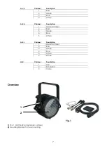
Page 9: ...ription 1 Master Dimmer 2 Red 3 Green 4 Blue 5 White Ar2 s Channel Description 1 Master Dimmer 2 Red 3 Green 4 Blue 5 White 6 Strobe HSV Channel Description 1 Hue 2 Saturation 3 Value Overview 1 2 Fig 1 1 18 x 1 Watt 6x Red 6x Green 6x Blue 2 Mountingbracket for Truss mounting ...

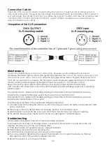
Page 10: ... DMX signal connector OUT 4 5 6 7 Note You cannot plug a standard DMX cable directly into the connector Be sure to use the included special cable for DMX connection Female 3 pin DMX to special 3 pin Male Male 3 pin DMX to special 3 pin Female Powercable to special 3 pin Female ...

Page 11: ...serial data link must be daisy chained in one single line To comply with the EIA 485 standard no more than 30 devices should be connected on one data link Connecting more than 30 fixtures on one serial data link without the use of a DMX optically isolated splitter may result in deterioration of the digital DMX signal Maximum recommended DMX data link distance 100 meters Maximum recommended number ...

Page 12: ...SSING 1 Connect a DMX controller example 50720 Showdesigner 1024 to the series of Spectral D4000 s 2 Each Spectral D4000 has 11 DMX channels DMX address LED Par 1 1 Par 2 12 Par 3 23 Par 4 34 etc 3 The ID address has not been set so therefore when using the controller CH11 must be inactive CH11 0 It is also possible to deactivate the ID address by selecting ID OFF from the Settings menu 4 Any DMX ...

Page 13: ...esigner 1024 50720 Example 1 The figure above shows a simple DMX layout All the Spectral D4000 s have different ID addresses which allows the user to collectively control the whole group of Spectral D4000 s with the same DMX address by setting CH11 to 0 or to control each Spectral D4000 independently by first selecting the DMX address and then by using CH11 to locate the target ID address S howdes...

Page 14: ...12 MENU OVERVIEW ...

Page 15: ...DOWN buttons to change the static colors Red Green Blue White or the strobe speed 0 20Hz Press MENU to go 1 step back You can combine RED GREEN BLUE and WHITE to create an infinite range of colors 0 255 Red White Set the value of the red LEDs 0 255 Set the value of the white LEDs 0 255 Green Strobe Set the value of the green LEDs 0 255 Set the value of the flash 0 20Hz Blue Set the value of the bl...

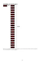
Page 16: ...14 Activating an Auto Program When you press ENTER in menu Auto Program you can choose one of the 10 built in programs You can also edit 10 custom programs ...

Page 17: ...ration the RUN MODE does not work DMX 512 Address When you press ENTER in menu DMX 512 address you can set the DMX address You can choose your DMX address between 0 512 Personality Enter the PERSONALITY mode to select a DMX mode STAG ARC1 AR1d ARC2 AR2d AR2s HSV STAG 11 channels ARC1 3 channels AR1d 4 channels ARC2 4 channels AR2d 5 channels AR2s 6 channels HSV 3 channels ID Address Enter the ID A...

Page 18: ...r the EDIT CUSTOM mode to edit the custom programs PR01 PR10 Each custom program has 30 steps which can be edited Each step allows the creation of a scene using RED GREEN BLUE WHITE STROBE TIMER FADE Changing the Settings ...

Page 19: ...n set This means RGB 255 255 255 The color is displayed as you have calibrated the specific color in menu CAL2 RGBW When it is set to NO on RGB 255 255 255 the RGB values are not adjusted and the output is most powerful The RGB s parameter can be adjusted in CAL2 5 Enter POW menu to choose NORM or HIGH power operation mode When the Spectral D4000 is in normal mode the power consumption is about 90...

Page 20: ...hite color will be made by the actual RGB values on the CAL2 Menu Activate Password Enter the KEY LOCK mode to select whether the access password is On or Off The Access Password UP DOWN UP DOWN When you have pressed ENTER in menu KEY ON it will take 30 seconds before the LED Par is locked When the password is activated the display will ask for password each time the fixture is powered on ...

Page 21: ...ues Use Up Down to change the values Use Up Down to change the values Use Up Down to change the values Use Up Down to change the values Use Up Down to change the values Use Up Down to change the values And so you can add a maximum of 30 scenes After that you can start with PR02 and create a maximum of 30 scenes again You can repeat these steps until you ve reached PR10 step 30 This means it is pos...

Page 22: ...Red Down Green 100 Blue 0 Red 0 Green 100 Blue Up Red 0 Green Down Blue 100 Red Up Green 0 Blue 100 Red 100 Green 0 Blue Down Red 100 Green Up Blue Up Red Down Green Down Blue 100 Red 100 Green 100 Blue 100 White 100 White 1 3200K White 2 3400K White 3 4200K White 4 4900K White 5 5600K White 6 5900K White 7 6500K White 8 7200K White 9 8000K White 10 8500K White 11 10000K 7 000 010 Strobe No Functi...

Page 23: ...currently projected color When the fader is at 255 the intensity of the output is at its maximum RED GREEN BLUE WHITE SELECTION Channels 2 3 4 and 5 control the overall intensity of each respective color Channels 2 3 4 and 5 can be combined to create an unlimited range of colors COLOR MACROS WHITE BALANCE Channel 6 selects the required COLOR MACRO and whites in different colors Channel 6 has prior...

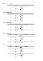
Page 24: ...ontrol ARC2 Channel Value Function 1 000 255 Red 0 100 2 000 255 Green 0 100 3 000 255 Blue 0 100 4 000 255 White 0 100 DMX Control AR2 d Channel Value Function 1 000 255 Dimmer 0 100 2 000 255 Red 0 100 3 000 255 Green 0 100 4 000 255 Blue 0 100 5 000 255 White 0 100 DMX Control AR2 s Channel Value Function 1 000 255 Dimmer 0 100 2 000 255 Red 0 100 3 000 255 Green 0 100 4 000 255 Blue 0 100 5 00...

Page 25: ...ddress 11 234 ID address 45 120 129 ID address 12 235 ID address 46 130 139 ID address 13 236 ID address 47 140 149 ID address 14 237 ID address 48 150 159 ID address 15 238 ID address 49 160 169 ID address 16 239 ID address 50 170 179 ID address 17 240 ID address 51 180 189 ID address 18 241 ID address 52 190 199 ID address 19 242 ID address 53 200 209 ID address 20 243 ID address 54 210 ID addre...

Page 26: ...24 Beam Angles ...

Page 27: ...ectric power The operator has to make sure that safety relating and machine technical installations are to be inspected by an expert after every year in the course of an acceptance test The operator has to make sure that safety relating and machine technical installations are to be inspected by a skilled person once a year The following points have to be considered during the inspection 1 All scre...

Page 28: ... 15 060 91 2 m Power and current 230 V 50 Hz 178 9 W 0 78 A operating 0 81 A inrush Double bracket yoke doubles as floor stand Operating modes 11 channel STAG Master Dimmer RGBW Color Macro Strobe Auto Custom Programs Auto Speed Adjustment Dimmer Speed ID Address Selection 3 channel ARC 1 RGB 4 channel AR1 d Master Dimmer RGB 4 channel ARC 2 RGBW 5 channel AR2 d Master Dimmer RGBW 6 channel AR2 s ...

Page 29: ......

Reviews: