26
ENG
S.H.S. s.r.l. Via F.lli Rosselli, 29 20027 Rescaldina (MI) – ITALY
Tel. +39 0331 466918 Fax. +39 0331 466147 www.shsitalia.it
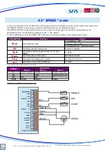
4.2 “ SPEED ” mode
To the uprising front of the START (IN1 or IN2) signal, the drive will start the motor with a ramp to the speed set to
the SPEED (AN-IN1) analog input, and in the direction defined to the DIR (IN3) signal.
The SPEED (AN-IN1) analog signal defines in every time the target speed for the motot, proportional to the
maximum speed set in the relative parameter (10V → max RPM)
To the downrising front of the START (IN1), the drive will stops the motor with a ramp to the 0 speed.
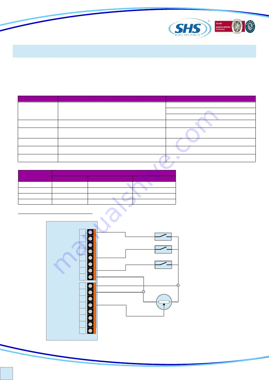
TYPICAL APPLICATION (Mode 4)
SIGNAL
FUNCTION
Mode 3
Mode 4
Mode 5
IN1
START / STOP
START
START/STOP CW
IN2
---
STOP
START/STOP CCW
IN3
DIR
DIR
---
AN-IN1
SPEED
SPEED
SPEED
PARAMETERS
Function
Values
Set of function mode
4 = Start/Stop + DIR
5 = Start + Stop + DIR
6 = Start/Stop CW + Start/Stop CCW
Set of the direction of the motor
0=Direct 1=Reverse
0 ÷ 9999
Set of the phase current [mA]
Step
full, half, 1/4, 1/8, 1/16
0 ÷ 9999
Func
dir
Spd
Set of the maximum speed referred to 10V input
[RPM]
Curr
vedi tabella modelli
Set of the microstepping [1/n steps]
Acc
Set of the acc/dec ramp [RPM/sec]
Nota: Other parameters doesn't affect in this mode.
+Vaux
GND
AN-IN1
COM IN1..3
IN3
IN1
DIR
START
SPEED
16
15
14
13
12
11
10
9
8
7
6
5
4
3
2
1
IN6/ENAB
IN5
IN4
COM I4...I6
IN3
IN2
IN1
COM I1...I3
+VAUX
GND
AN-IN2
AN-IN1
OUT3
OUT2
OUT1
COM OUT
ENABLE


