


P/N 1808684 Rev. I
18
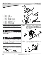
Electric Installation
- continued
TEST OPERATION
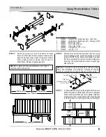
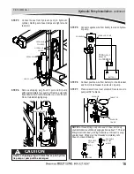
STEP 5:
Divide portion of dual-conductor wire into two single-
strand wires (see caution). Cut section of single-strand
wire to run from positive terminal on battery to circuit
breaker. Crimp 3/8" ring terminal
6
onto one end of
wire and 1/4" ring terminal
5
onto other end. Connect
3/8" ring terminal to positive battery post and connect
1/4" ring terminal to post on circuit breaker marked BAT.
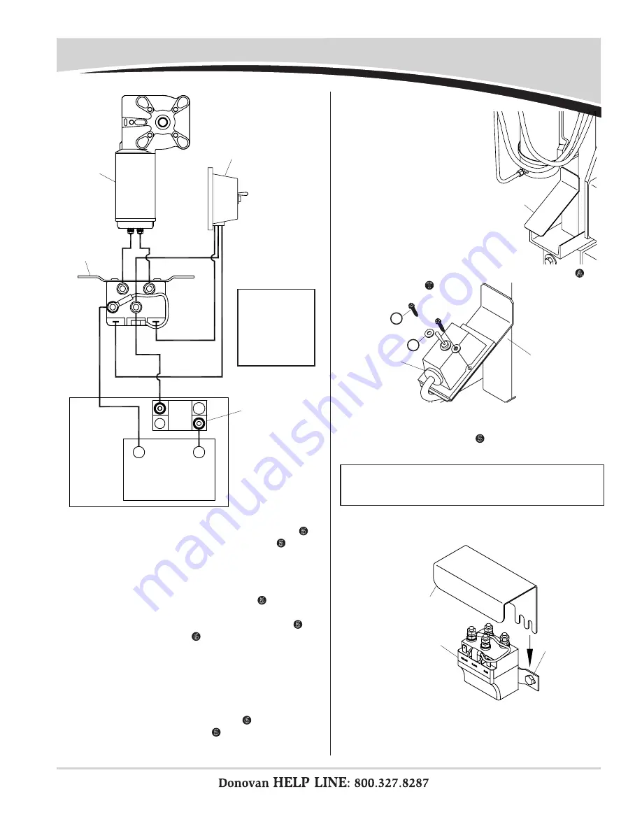
STEP 8:
Run three-strand jacketed toggle switch wire to sole
-
noid and cut to length. Connect wire ends to solenoid,
placing ring terminal
5
on post marked BATT+ and
two quick disconnects to tabs.
STEP 9:
Slide solenoid cover under bolt heads holding solenoid
in place. Tighten fasteners to hold cover and solenoid
in place.
STEP 10:
Operate toggle switch to verify tarp is moving in same
direction as shown on toggle. If tarp is not moving in
same direction as toggle, either swap two wires con
-
nected to tabs on solenoid or two wires connected to
motor.
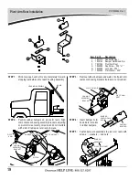
STEP 6:
Locate toggle switch
where switch can easily
be accessed by system
operator. Weld toggle
switch plate in place.
STEP 7:
Fasten toggle switch to plate with screws
A
and
washers
T
.
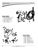
STEP 4:
Cut section of dual-conductor wire to run from solenoid
to battery. Crimp two 1/4" ring terminals
5
on one end of
wire and connect terminals to posts on solenoid marked
Batt+ and Batt-. Crimp one 1/4" ring terminal
5
and
one 3/8" ring terminal
6
on other end of wire. Connect
1/4" ring terminal to circuit breaker post marked AUX
and connect 3/8" ring terminal to negative battery post.
STEP 3:
Cut section of dual-conductor wire to run from solenoid
to electric motor. Crimp two 1/4" ring terminals
5
on
one end of wire and two 1/4" ring terminals
5
on other
end of wire. Connect 1/4" ring terminals to motor and
1/4" ring terminals to solenoid.
toggle
switch
plate
toggle
switch
plate
toggle
switch
solenoid
tighten
fasteners
solenoid
cover
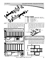
WIRING DIAGRAM
battery
solenoid
circuit
breaker
toggle
switch
direct
-
drive
motor
NOTE:
Refer to
wiring diagram
for steps 3, 4, 5
and 8. See note
and caution on
previous page.
NOTE:
Kit includes three extra butt connectors. If excess
switch wire cannot be coiled, connectors are provided to
shorten switch wires to desired length.
+
_
A
T