


Summary of Contents for SHUR COVER
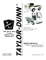
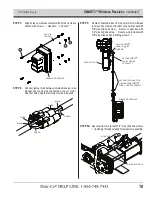
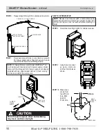
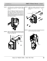
Page 1: ...Sheeting System w SMART3 P N 1127925 Rev B ...
Page 24: ......
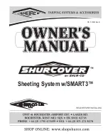
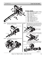
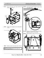
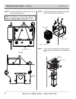
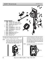
The Shur-Co SHUR COVER is an essential trucking accessory designed to protect your cargo from the elements. This Owner's Manual provides comprehensive instructions on how to install and operate the SHUR COVER, ensuring optimal usage. Download the free manual from our website and unlock the full potential of your SHUR COVER.
Page 1: ...Sheeting System w SMART3 P N 1127925 Rev B ...
Page 24: ......