English
1
ACCESS UHF SERIES USER GUIDE
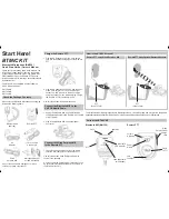
This user guide provides detailed instructions for your Access UHF series wireless system. To get your system up and
running in minutes, see the Access UHF Series Quick Set Up Guide.
Your new Access UHF Series system is designed to give you both the freedom of a wireless system and world-famous
Shure sound quality. This manual covers all four Access UHF Series systems: the AXU58D handheld systems; the AXUGD
bodypack systems; the AXUHD Headset systems; and the AXULD lavalier microphone system.
Wireless
System
Components
AXU58D
Hand-held systems for
singers
AXUGD
Bodypack systems for
electric guitar, bass, and
other electric instruments
AXUHD
Bodypack system for hands-
free applications, such as
aerobics instruction or
percussion
AXULD
Bodypack system for public
speaking, theater, or
business presentations
Transmitter:
AXU2 Hand-Held
Microphone-Transmitter
AXU1 Body-Pack Transmitter
Microphone:
SM58 Microphone
WL184 Supercardioid
Lavalier Microphone
WH20TQG
Headset Microphone
A302
Adapter Cable
Receiver:
AXU4 Diversity Receiver
Power Supply:
PS20 (105–125 VAC, 60 Hz), o PS20E (230 VAC, 50 Hz)
Battery:
9 V Alkaline (Duracell MN 1604)
Supplied
Accessories:
Microphone Stand Adapter,
Receiver Feet,
VELCRO
Receiver
Mounting Strips
Receiver Feet,
VELCRO Receiver Mounting
Strips
Receiver Feet,
VELCRO Receiver Mounting
Strips
Receiver Feet,
VELCRO Receiver Mounting
Strips
RECEIVER FEATURES
6
7
10
9
11
1
2
3
4
5
8
Á
Á
Á
Á
Á
Á
Á
ÁÁ
Á
Á
Á
Á
Á
Á
Á
Á
Á
Á
Á
Á
Á
Á
Á
Á
Á
Á
Á
Á
Á
Á
Á
Á
Á
Á
Á
Á
Á
Á
Á
Á
Á
Á
Á
Á
Á
Á
Á
Á
Á
Á
Á
12–18 VDC
DC INPUT
Á
Á
Á
Á
Á
Á
Á
Á
Á
Á
Á
Á
Á
Á
UNBALANCED
HIGH Z
BALANCED
LOW Z
LINE MIC
SQUELCH
MIN
MAX
.
.
.
. .
. .
.
.
.
FIGURE 1. AXU4 RECEIVER FEATURES
1. Power On Indicator: This green light glows when DC Power
ia applied to receiver.
2. Diversity A/B Indicators: These yellow lights glow when the
receiver detects RF signals from the transmitter. When only one
light glows, the signal is being received on only one antenna.
3. Audio Peak Indicator: This red light flickers when the receiver
audio output signal approaches the overload clipping level.
4. Volume Control: Increases or decreases receiver output
volume. It does not affect audio clipping levels.
5. Antennas: Receive RF signals from the transmitter. For best
performance, point the receiver antennas away from each
other at a 45
°
angle.
6.
1
/
4
” Phone Jack Connector (Unbalanced High Z Output):
An unbalanced audio cable with a
1
/
4
” phone plug (such as a
standard guitar cable) can be used between this connector and
your amplifier input.
7. XLR Audio Output Connector: Balanced low Z micro-
phone level output.
8. Mic/Line Switch: Switches output of XLR connector from
microphone level to line level. Use line level when connect-
ing receiver to a device without an available mic-level input,
such as a power amplifier, signal processor, or VCR.
9. Squelch Control: Adjusts squelch to enhance signal quality or
extend system range. This control is factory pre-set, and nor-
mally does not require further adjustment.
10. Power Input Connector: Mates with the AC power adapter.
11. Power Cable Retainer: Secures the AC adapter cable to the
receiver.


