96
User Manual
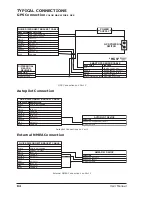
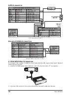
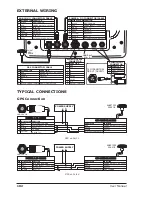
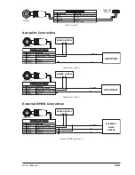
GPS Connection
DIFFERENTIAL
BEACON
RECEIVER
RTCM 104
SIGNAL RETURN
FUNCTION
QUICK DISCONNECT BRACKET CABLE
DESCRIPTION
WIRE COLOR
BLACK
RED
WHITE
GREEN
YELLOW
BROWN
GRAY
ORANGE
PINK
BLUE
POWER SUPPLY GND
POWER
NMEA0183/C-COM
NMEA0183/C-COM
NMEA0183/180/180CDX/C-COM
NMEA0183/C-COM
NMEA0183/180/180CDX/C-COM
NMEA0183/C-COM
NMEA0183/180/180CDX/C-COM
SIGNALS RETURN
GND/COMMON
POWER +10-35Vdc
INPUT1-
SIGNAL - (common/return)
FUNCTION
SMART GPS SENSOR CABLE
WIRE COLOR
RED
BROWN
GREEN
WHITE
BLACK/YELLOW/SHIELD
POWER +10-35 Vdc
GPS NMEA0183
GPS NMEA0183 INPUT+
RTCM 104 INPUT+
GND/SIGNAL RETURN
FUNCTION
POWER
SMART GPS
SENSOR
GPS POWER
SWITCH
GPS Connections on Port 3
External NMEA Connection
External NMEA Connections on Port 1
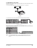
C-COM GSM Plus Connection
To connect the modem C-COM to the chart plotter with quick disconnect bracket
follow the procedure:
1. Cut the C-COM cable about about 1.96" [5 cm] from the "T" connector:
2. Connect the wires to the quick disconnect bracket cable as follows:
Summary of Contents for COLOR MAX 15
Page 20: ...22 User Manual...
Page 56: ...58 User Manual...
Page 58: ...60 User Manual...
Page 78: ...80 User Manual...
Page 84: ...86 User Manual...
Page 96: ...98 User Manual...


