background image


Manu_ENG_UFO_ rev. 0_04_2012 

pag. 6 

TECHNICAL  DATA 


Appliance model

UFO EB /08

UFO M /08

Electric feeding

230 Volt - 1phase - 50 Hz

NO

MAX feeding pressure

(mbar)

50,0

50,0

Gas group

nr.

1

1

Gas connection

1 x 3/8"

1 x 3/8"

Absorbed power

(Watt)

24

NO

NOx class

4

4

Weight

(kg)

10

10

Cover diameter

(mm)

800

800

Height

(mm)

650

650

Remote control

(mm)

option

option

GAS G20
Heat input MAX (Hs)

(kW)

9,4

9,4

Heat input MAX (Hi)

(kW)

8,5

8,5

Heat input MIN (Hs)

(kW)

7,1

-


Heat input MIN (Hi)

(kW)

6,4

-


GAS supply pressure

(mbar)

20,0

20,0

NOZZLE pressure MAX

(mbar)

15,0

15,0

NOZZLE pressure MIN

(mbar)

9,0

-


Gas consumption MAX

(Sm

3

/h)

0,90

0,9

Gas consumption MIN

(Sm

3

/h)

0,68

-


Nozzle diameter

(mm)

2,30

2,3

GAS G30
Heat input MAX (Hs)

(kW)

10,8

10,8

Heat input MAX (Hi)

(kW)

10,0

10,0

Heat input MIN (Hs)

(kW)

8,1

-


Heat input MIN (Hi)

(kW)

7,5

-


GAS supply pressure

(mbar)

30,0

20,0

NOZZLE pressure MAX

(mbar)

27,7

27,7

NOZZLE pressure MIN

(mbar)

15,5

-


Gas consumption MAX

(kg/h)

0,79

0,8

Gas consumption MIN

(kg/h)

0,59

-


Nozzle diameter

(mm)

1,60

1,6

GAS G31
Heat input MAX (Hs)

(kW)

10,9

10,8

Heat input MAX (Hi)

(kW)

10,0

10,0

Heat input MIN (Hs)

(kW)

8,2

-


Heat input MIN (Hi)

(kW)

7,5

-


GAS supply pressure

(mbar)

37,0

37,0

NOZZLE pressure MAX

(mbar)

35,9

35,9

NOZZLE pressure MIN

(mbar)

20,0

-


Gas consumption MAX

(kg/h)

0,78

0,8

Gas consumption MIN

(kg/h)

0,58

-


Nozzle diameter

(mm)

1,60

1,6


IMPORTANT: "GAS supply pressure", defined as the dynamic pressure of the circuit
or part of the circuit downstream of the pressure reducer, with all the appliances running

and must be detected in this condition. With lower pressure difficulties in start-up may 
occur.


Summary of Contents for UFO EB/08

Page 1: ...90384081 E mail commerciale siabs it via Del Lavoro 7 Fax 39 02 9029538 Web site www siabs com 20010 Casorezzo MILAN Infra red Gas Heaters MANUAL for INSTALLATION RUNNING and MAINTENANCE Models UFO EB 08 and UFO M 08 Version UFO 08 ...

Page 2: ... flammable surfaces 9 assembling 10 connection to GAS supply 11 connection to ELECTRIC feeding 12 SIT control unit TWO STAGE version 13 and 14 SIT control unit wiring diagram TWO STAGE version 15 Put in operation and First Start up 16 to 19 appliances version UFO EB 08 electronic start up two stages 17 and 18 appliances version UFO M 08 manual start up on off 19 Maintenance and Annual Check 20 to ...

Page 3: ... instructions by the Manufacturer incorrect installation can cause damage to people animals and things the Manufacturer doesn t accept any contractual and extra contractual liability in tort and contract for damages caused by errors in installation and use use only original accessories and modification kits after you have removed all items from packing box make sure that all components have been i...

Page 4: ...e are subject to the conditions of the original warranty The guarantee is only the free supply on Ex Works basis of parts with manufacturing or workmanship defects The guarantee does not cover problems due to carelessness incorrect setting misuse of the appliance or fortuitous accidents and not dependent on imperfection processing or defective materials and those due to dismantling or changes with...

Page 5: ...th technical data do not remove placed on the cover of the gas group Apparatus type A1 gas category II 2H3P Plate label f e appliance UFO E B 08 electronic start up version two stages G20 gas Essential features of the appliance are given on the packing label outside on the packing box ...

Page 6: ...ut MAX Hs kW 10 8 10 8 Heat input MAX Hi kW 10 0 10 0 Heat input MIN Hs kW 8 1 Heat input MIN Hi kW 7 5 GAS supply pressure mbar 30 0 20 0 NOZZLE pressure MAX mbar 27 7 27 7 NOZZLE pressure MIN mbar 15 5 Gas consumption MAX kg h 0 79 0 8 Gas consumption MIN kg h 0 59 Nozzle diameter mm 1 60 1 6 GAS G31 Heat input MAX Hs kW 10 9 10 8 Heat input MAX Hi kW 10 0 10 0 Heat input MIN Hs kW 8 2 Heat inpu...

Page 7: ...re a sufficient air change the flow of air needed can be calculated using the following equation UNI EN 13410 Vtot Qnb x L Vtot air change flow rate in m3 h Qnb total heating power installed in the premises in kW L air change coefficient must be 10 m3 h kW IMPORTANT air change coefficient L to be used MUST NOT be lower than 10 m3 h for each kW of installed power For NO reason the appliance s can b...

Page 8: ...led in vertical position Handling During extraction of the appliances from package and for all operations of handling till final place of installation must NOT be used as lifting points the gas group cover gas valve flame control the cover the flexible gas pipe and the electric cable Appliances must be taken at the installation point height using the tube structure or the drilled plate welded on t...

Page 9: ... C Above MINIMUM heights of installation are indicative consult us each case to select the most advisable unit and the best height of installation mostly for limit values MINIMUM distances from flammable surfaces IMPORTANT flammable materials inside the radiation could begin to burn and cause fires Minimum distances of installation must be respected between the heating surface of the appliances an...

Page 10: ...nd washer from the M8 pin fixed on the upper part of the burner Picture 3 Picture 3 Place the cover Picture 4 place the washer on the cover and use a CH13spanner to tighten the M8 nut to fix the cover Picture 5 Picture 4 Picture 5 IMPORTANT once installation is finished check that power supply cable is not in contact with the aluminium cover warm while appliance is running ...

Page 11: ...detected in this condition With lower pressure difficulties in start up may occur Once the connection is made in compliance with the rules in force in the country of installation a verify the sealing of hydraulic pipes and gas connection to the unit b check that the pressure is correct c make sure that the apparatus functions in the conditions for which it was prepared UFO EB 08 electronic start u...

Page 12: ...f the power supply line or refer to the data given in the plate label of the heater In any case use a cable with minimum section 4x1 5mm2 TWO STAGE version The wiring diagram is shown on page 15 of this manual For the electrical connection unlock the plug and unscrew its case connect a cable according to the indications given on the terminal plug namely L1 phase wire N neutral wire earth wire L2 m...

Page 13: ... you will find the data heat input pressure and gas flow rate referring to the appliances with TWO STAGE version in the tables at page 6 of this manual N B MINIMUM heating capacity feed L1 N MAXIMUM heating capacity feed L1 L2 N You will find the data heat input pressure and gas flow rate referring to the appliances with TWO STAGE version in the tables at page 6 of this manual The TWO STAGE versio...

Page 14: ...ressure regulator Act as shown in picture 2 on the CH10 screw for setting of the maximum pressure till you get the required pressure turn clockwise to increase and counter clockwise to decrease Take out tension at the pressure modulator and with a screw driver act on the inner screw for minimum setting picture 3 till you get the required pressure turn clockwise to increase and counter clockwise to...

Page 15: ...Manu_ENG_UFO_ rev 0_04_2012 pag 15 WIRING DIAGRAM SIT control unit TWO STAGE ...

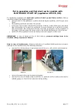
Page 16: ... the plate of the characteristics of the appliance check the correct mounting of gas group gas valve and flame control only for appliance UFO EB 08 with electronic start up check that the power electric line has been correctly sized which has been respected phase neutral polarity and that the cable grounding is connected only for appliance UFO EB 08 with electronic start up make sure the mechanica...

Page 17: ...fter that period of time the start up sequence can be repeated if the heater continues going into block refer to the section Maintenance of this manual switch off of the appliance is done by taking out power supply to control unit IMPORTANT in case of failure at time of first start up pressure settings have to be checked acting on pressure intakes Only in case of maintenance following instruction ...

Page 18: ...wise to increase and counter clockwise to decrease Picture 3 Picture 4 the new and correct nozzle pressure should be checked at intake pressure Picture 5 disconnect the pressure gauge and close the screw of intake pressure Picture 6 Picture 5 Picture 6 reassemble the cap of the regulator and place a new suitable seal Picture 7 mount the gas group cover Picture 8 and tight the 4 fixing screws Pictu...

Page 19: ...se of failure at time of first start up pressure settings have to be checked acting on pressure intakes Only in case of maintenance following instruction of qualified SIABS personnel pressure settings can be modified using the following procedure unscrew the screw of intake pressure and connect a suitable gauge to check correct pressure during setting Picture 3 remove the cap of pressure regulator...

Page 20: ...rical connections search for possible losses on the gas circuit and gas valve check of gas pressure at nozzle general control of all components of the appliance control of openings and ventilation systems natural and or mechanical control of alarm signals if any If the appliances are installed in dusty environments is advisable to clean more frequently the burners blowing compressed air with LOW H...

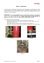
Page 21: ...G30 to G20 natural gas it is compulsory to change also the plate label with technical data placing a new label with the new data repeat checks listed at page 20 PUT IN OPERATION and FIRST START UP afterwards put seal again after operation To change the gas nozzle act as follows unscrew the 2 fixing screws and take out the protection grid Picture 9 unscrew the 4 screw in the lower part not loosen t...

Page 22: ...e the ceramic plates D the heater doesn t turn D1 Interruption in the elctric plant D1 Verify voltage at connector of power suppy because no gas is getting D2 No tension D2 Replace the control unit D3 Solenoid valve is live but coils D3 Replace the gas valve are not energized E the ignition electrode doesn t E1 The electrode doesn t spark because E1 Adjust distance closer or further between sparkl...

Page 23: ...USERS Implementation of Directives 2002 95 EC 2002 96 EC and 2003 108 EC relating to the use of hazardous substances in electrical and electronic equipment as well as waste disposal The product at the end of its useful life must be separated from other waste You should therefore give the equipment at end of its working life to appropriate separate collection centres of electric and electronic wast...

Page 24: ...Manu_ENG_UFO_ rev 0_04_2012 pag 24 CE certificate ...

Page 25: ...Manu_ENG_UFO_ rev 0_04_2012 pag 25 DATE and STAMP OPERATION NOTES OPERATION NOTES DATE and STAMP DATE and STAMP OPERATION NOTES DATE and STAMP OPERATION NOTES ...

Page 26: ...MILAN ITALY ___________________________________________________________________________ to contact us Phone 39 02 90384081 Fax 39 02 9029538 E mail commerciale siabs it Web page www siabs com Continuous development to improve the product could cause changes of above without notice ...

Reviews: