background image

www.sibotech.net

- 20 -

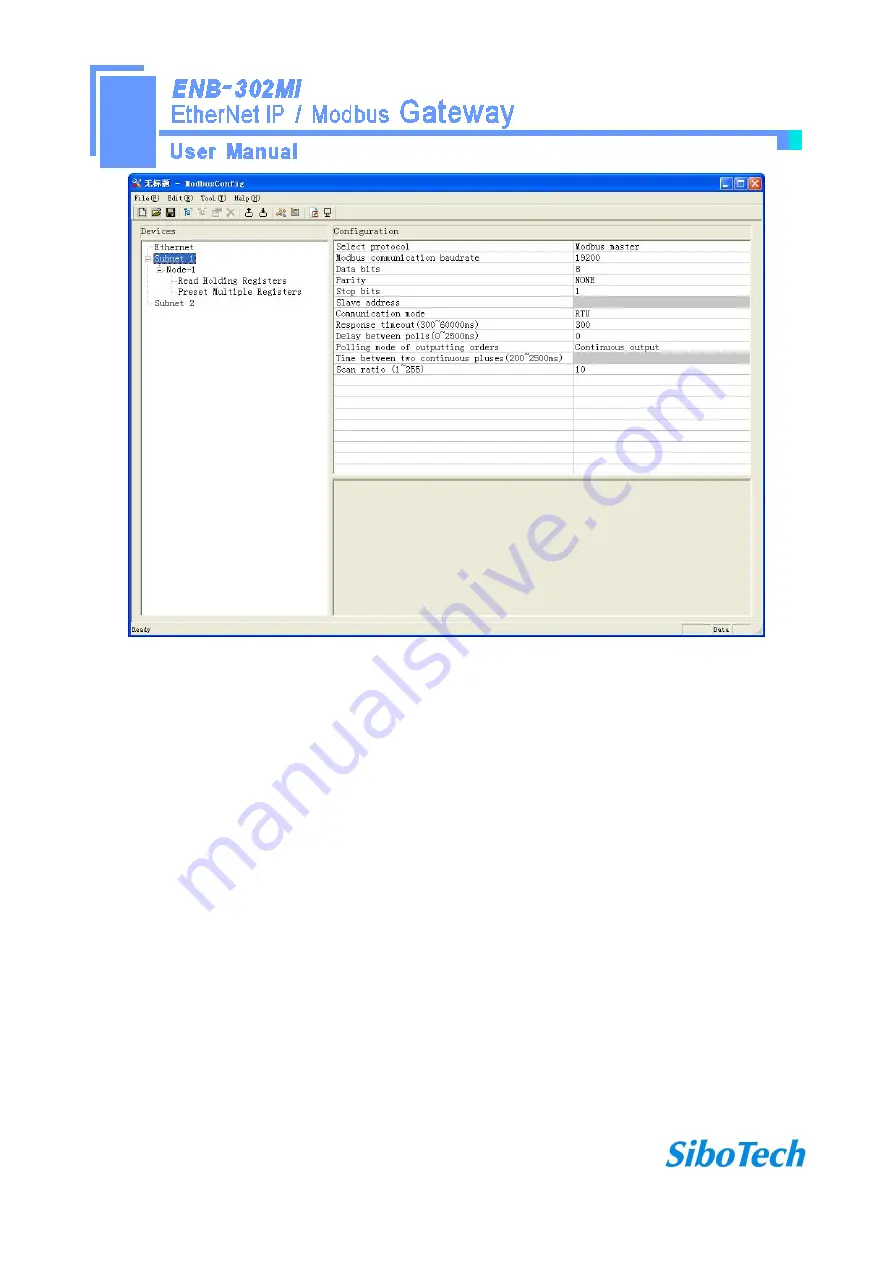
Modbus communication baud rate: There are 300, 600, 1200, 2400, 9600, 19200, 38400, 57600 and

115200bps to be selected.

Data bits: 8 bits

Parity check mode: There are none, odd, even, mark and space to be selected.

Stop bits: There are 1 and 2 to be selected.

Transmission mode: There are RTU and ASCII to be selected.

Response timeout: When the Modbus master send commands, the time waiting for response from the slave,

the range is 300~60000ms.

Delay between polls: After an command of Modbus having been sent and having received correct response,

the time before next command being sent, the range is: 0 ~ 2500ms.

Polling mode of outputting command:

Modbus writing command (output command) has 4 kinds of outputting modes: Continuous output, 0utput disable,

Change-of–state output, Pulse output, Communication port

Summary of Contents for ENB-302MI

Page 1: ...EtherNet IP Modbus Gateway ENB 302MI User Manual REV 1 1 Sibotech Automation Co Ltd Technical support 86 021 5102 8348 E mail support sibotech net ...

Page 2: ...oftware 13 4 1 Notes before configurating 13 4 2 User interface 14 4 3 Operation of equipment view 16 4 3 1 Equipment view interface 16 4 3 2 Operation mode of equipment view 17 4 3 3 Operation types of equipment view 17 4 4 The operation of configuration view 18 4 4 1 Interface of Ethernet configuration view 18 4 4 2 Interface of subnet configuration view 19 4 4 3 Interface of node configuration ...

Page 3: ...oject 29 4 7 2 Load the configuration project 29 4 8 Output excel document 29 4 9 Debug 30 5 EtherNet IP Connection Parameters 33 6 Typical Application 34 7 Installation 35 7 1 Mechanical Dimensions 35 7 2 Installation 35 8 Attention 37 9 Copyright Information 38 10 Related Products 39 ...

Page 4: ...ation software GT 123 1 3 Technical specification 1 EtherNet IP network is independent with two Modbus networks 2 Ethernet 10 100M adaptive 3 Support IP addresses conflict detection function 4 Support the ODVA Standard EtherNet IP communication protocol 5 Two serial RS485 interfaces half duplex and baud rate support 1200 2400 4800 9600 19200 38400 57600 115200 parity mode support none odd even mar...

Page 5: ...tical isolation 8 The maximum number of input and output bytes of EtherNet IP Maximum number of input bytes 512Bytes Maximum number of output bytes 512Bytes 9 Power supply 24VDC 11V 30V 90mA 24VDC 10 Working temperature 20 60 relative humidity 5 95 no condensation 11 Dimensions 40mm width 125mm height 110mm depth 12 Installation 35mm rail 13 Protection class IP20 14 Test standard EMC test standard...

Page 6: ...r supply when the way in which the power fails the other way you can continue to supply power to ensure normal operation Power supply wiring as shown below GND NC 24V 1 2 3 GND 24V DC power 24V Ⅰ Power interface of ENB 302MI GND NC 24V 1 2 3 GND 24V Optionally be connected Must be connected Power interface of ENB 302MI the other DC power 24V Ⅱ 2 2 Connect serial devices RS485 connection as shown b...

Page 7: ...gnal reflection and interference in RS485 multipoint communication adding one terminal resistor at the both farthest ends of the line is necessary and the argument is 120Ω 1 2W Note There is no internal termination resistor in the RS485 interface of ENB 302MI 2 3 Ethernet connection Ethernet interface apply RJ 45 connector 10 100M adaptive ...

Page 8: ... On Operation mode read and write configuration data against On Off or On Configuration mode IP address is fixed at 192 168 0 10 this mode can only read and write configuration data can not communication between EtherNet IP and Modbus network 2 5 Installing software Take the product CD into the computer CD drive open the CD install the configuration software GT 123 You can easily follow the prompt...

Page 9: ...onnection is not established Always red IP address indicates a conflict Red flashing EtherNet IP connection timed out DHCP BOOTP IP address conflict detection SNS Always green Modbus Communication normal Always red At least one Modbus network response timeout exception or error Ethernet RJ 45 interface RS 485interfaceⅠ RS 485interfaceⅡ Configuration switches Power interface Indicator ...

Page 10: ...it 1 Function bit bit 2 Description Off Off Operation mode allowing read and write configuration data Off On Operation mode read and write configuration data against On Off or On Configuration mode IP address is fixed at 192 168 0 10 this mode can only read and write configuration data can not communication between EtherNet IP and Modbus network Note Restart ENB 302MI after resetting the configura...

Page 11: ... Pin Signal Description S1 TXD Tranceive Data Output S2 TXD Tranceive Data Output S3 RXD Receive Data Input S4 Bi directional Data S5 Bi directional Data S6 RXD Receive Data Input S7 Bi directional Data S8 Bi directional Data 3 4 3 RS 485 interface The RS 485 interface of ENB 302MI is standard and the RS 485 characteristics of the product are shown as follows ...

Page 12: ...ion without repeater and can up to 127 stations with RS485 repeater Plug connection 3 pin pluggable terminal 2 The main points on RS 485 transmission equipments installation All the equipments be connected with RS 485 bus Subsection can be connected up to 32 sites The farthest end of each bus has a termination resistor 120Ω 1 2W to ensure reliable operation of the network Serial interface uses 3 p...

Page 13: ...figurate a variety of fieldbus gateway devices including PM 120 MD 21 SS 430 PM 160 ENB 302MI and other products It can set related parameters and commands of Modbus and other bus The document mainly introduces the use method of ENB 302MI Double click the icon to enter the main interface of the software Choose ENB 302MI to enter configuration interface ...

Page 14: ...tech net 14 4 2 User interface GT 123 interface include title bar menu bar toolbar status bar equipment section configuration section and notes section Note All the gray part in the software can not be changed ...

Page 15: ...Save Save the current configuration Add nodes Add a Modbus slave node Delete nodes Delete a Modbus slave node Add commands Add a Modbus command Equipment section can choose the operating targets including fieldbus or sub network and add the nodes and commands Menu bar Toolbar Title bar Configuration section input configuration parameters gray part can not be modified while white part can be modifi...

Page 16: ...nload the configuration from the software to the module Conflict Detect Detect whether there is conflict in memory data buffer of the gateway Output Excel document Output the current configuration to local hard disk and save it as xls file Debug For debugging Modbus communications and defining the network fault 4 3 Operation of equipment view 4 3 1 Equipment view interface ...

Page 17: ...f adding a new node Then there is a new node named new node under subnet 2 Delete nodes Right click on the node to be deleted and then perform the operation of deleting the node The node and its all commands will be deleted 3 Add commands Right click on the node and then perform the operation of adding command to add a command for the node The dialog box will be shown as follow Currently it suppor...

Page 18: ...Interface of Ethernet configuration view In the interface of device view click Ethernet and then the configuration view is shown as follows Configurable items include IP setting method IP address subnet mask gateway address DNS1 DNS2 IP setting method static configuration BOOTP DHCP can be selected IP Address Set the device IP address Subnet Mask Set subnet mask of the device Gateway Address Set g...

Page 19: ...as follows Modbus communication baud rate Data bits Parity check mode Stop bit Transmission mode Response timeout Delay between polls Polling mode of outputting commands Time between two continuous pluses the polling mode of outputting commands is pulse output Scanning ratio Interface of configuration view is shown as follow ...

Page 20: ...ASCII to be selected Response timeout When the Modbus master send commands the time waiting for response from the slave the range is 300 60000ms Delay between polls After an command of Modbus having been sent and having received correct response the time before next command being sent the range is 0 2500ms Polling mode of outputting command Modbus writing command output command has 4 kinds of outp...

Page 21: ...rrect response Pulse output Output the write command according to the pulse period Scan ratio Ratio of slow scan and quick scan If the quick scan command sends 10 times slow scan command sends 1 time 4 4 3 Interface of node configuration view In the interface of device view left click a node and then configuration interface is shown as follow 4 4 4 Interface of command configuration view In the in...

Page 22: ...buffer of the module The address range of data mapping in the module memory Read command 0x0000 0x01FF Write command 0x4000 0x41FF When write command is used exchanging locally it also can use 0x0000 0x01FF Bit offset of memory mapping 0 7 For the bit operation commands the position range of start bit byte is 0 7 Bytes swap There are three kinds of type No swapping two bytes swapping four bytes sw...

Page 23: ... scan is equal to quick scan being multiplied by scan ratio Configure it in the interface of subnet configuration interface 4 4 5 Notes View Notes view displays the explanation of configuration The notes that show how to configurate the starting address of memory mapping is shown as follow 4 5 Conflict detect For the detection of whether there is conflict of the starting address of memory mapping ...

Page 24: ...e command can select the check box and in the memory mapping area it can show the corresponding share of spatial location Click the command again will remove the selected box and it doesn t show the mapping location The function can be used to conflict detect of memory mapping area 4 5 2 Operation of memory mapping area Memory mapping area is divided two parts input area and output area Input mapp...

Page 25: ...ea no conflict Red Output area or input area different commands occupy the same byte address the byte is shown as red For bit operation commands the meanings of above shows are also applicable Click the input output regional grid whether the grid is occupied or not is shown as follows 4 6 Hardware communication Hardware communications menu items are shown as follow 4 6 1 Ethernet configuration Use...

Page 26: ... feature users must specify their own devices to connect to in the configuration when the upload or download only lists the devices Note Please click OK button to confirm click Cancel button will be enabled as a search function 4 6 2 Upload configuration Choose to upload configuration dialog box will pop up the search appliance ...

Page 27: ...net 27 Select the device you want to configure and click Log on then enter the upload dialog box Gateway configuration information will be uploaded to the software from the device the display interface is as follows ...

Page 28: ...www sibotech net 28 4 6 3 Download configuration Download configuration and upload configuration similarly Note Before downloading make sure all the configuration has been completed and correct ...

Page 29: ...t Select Save can save the project 4 7 2 Load the configuration project Select Open and then you can open a project 4 8 Output excel document Excel document helps users to examine the configuration related Choose the icon save the configuration as excel document and choose the right path ...

Page 30: ...www sibotech net 30 4 9 Debug This function is used to monitor the gateway memory data Use the feature the dialog box will pop up the search appliance ...

Page 31: ... the device you want to configure and click Log on then enter the debug dialog Display interface as follows Memory mapped address Memory starting address of writing data in the gateway Data Data being written to memory of gateway Users can debug Modbus communication through transmitting data When Modbus slave has no response or time out ...

Page 32: ...www sibotech net 32 ...

Page 33: ...s Gateway provides the connection parameters are as follows Input Instance 102 128Bytes 112 256Bytes 122 512Bytes Output Instance 101 128Bytes 111 256Bytes 121 512Bytes Configuration Instance 113 10Bytes The parameters being configured in RSLogix5000 below ...

Page 34: ...www sibotech net 34 6 Typical Application ENB 302MI can connect Modbus devices to the EtherNet IP network and achieve communication between PLC or PC with EtherNet IP interface and Modbus devices ...

Page 35: ...www sibotech net 35 7 Installation 7 1 Mechanical Dimensions Size 40mm width 125mm height 110mm depth 7 2 Installation 35mm DIN rail mounting ...

Page 36: ...www sibotech net 36 ...

Page 37: ...amage To prevent bump module may damage internal components Power supply voltage control in the prospectus within the scope of the requirements to burn module To prevent water water module will affect the normal work Please check the wiring before any wrong or short circuit ...

Page 38: ...ion Sibotech maybe upgrades the product without notifying users is the registered trade mark of SiboTech Automation Co Ltd The product has many applications The users must make sure that all operations and results are in accordance with the safety of relevant field and the safety includes laws rules codes and standards ...

Page 39: ...botech net 39 10 Related Products Related products include ENB 302MT PM 160 and so on More information about these products please visit http www sibotech net En or dial technical support line 86 21 5102 8348 ...

Reviews: