background image

HART/ PROFIBUS-DP Gateway

HPM-610

User Manual

REV 1.5

SiboTech Automation Co., Ltd.

Technical Support: +86-21-5102 8348

E-mail: gt@sibotech.net

Summary of Contents for HPM-610

Page 1: ...HART PROFIBUS DP Gateway HPM 610 User Manual REV 1 5 SiboTech Automation Co Ltd Technical Support 86 21 5102 8348 E mail gt sibotech net...

Page 2: ...n 11 3 3 3 Internal external sampling resistance switch 11 3 4 Interface 12 3 4 1 Power Interface 12 3 4 2 PROFIBUS DP interface 12 3 4 3 RS485 RS422 interface 12 3 4 4 RS 232 interface 14 3 4 5 HART...

Page 3: ...ta 39 5 3 Trigger Command 40 5 4 Data Exchange with PROFIBUS DP 41 5 5 Data Exchange with MODBUS 41 6 In STEP7 Access Data of Gateway and Select Data Module 42 6 1 How STEP7 access data of gateway 42...

Page 4: ...n HART and serial RS232 RS485 RS422 Abundant debug function Direct display of data exchange command diagnosis of HART slave and common debugging these function are very convenient for user s communica...

Page 5: ...rsal mode and achieve transparent data transmission with HART slave devices 15 Power 24VDC 9V 30V 80mA 24VDC 16 Operating Temp 40 F to 158 F 40 C to 70 C Rel Humidity 5 95 non condensing 17 External d...

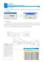
Page 6: ...way and the serial port of the computer with the serial cable in the package box Wiring methods refer to section 3 4 3 of this manual 3 Install the configuration software HT 123 4 Power it on the digi...

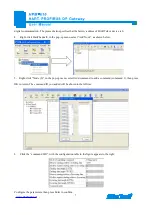
Page 7: ...in the figure appears to the right Then you can completed the configuration of HART network Notes HART protocol specifies that the slave device which address is 0 must work in single point mode this a...

Page 8: ...e pop up menu select Add Node as shown below 5 Right click Node 0 in the pop up menu select Add command to add a command command 1 then press OK to return The command ID you added will be shown in the...

Page 9: ...mens S7 300 series PLC the modeling software uses STEP7 In data exchange window you can see the main variable value of the pressure transmitter RS232 Interface 24V power supply Pressure transmitter 25...

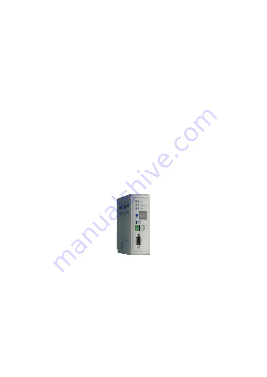
Page 10: ...This picture is for reference only Product appearance should accord to the real object PROFIBUS Interface HART Interface 24VDC Interface RS485 RS422 Interface Indicators DIP switch State address disp...

Page 11: ...switch Configuration switch is located at the bottom of product bit 1 is the debugging bit and bit 2 is the configuration bit The debugging bit 1 Configuration bit 2 Description Off Off Running mode...

Page 12: ...s was set successfully After coming in the status of setting PROFIBUS MODBUS address if no button action within ten seconds HPM 610 exits the status of setting address automatically and continues to d...

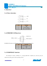
Page 13: ...interface uses DB9 male connector and the pins are defined as follows Pin Function 3 PROFI_B Data positive 5 GND 8 PROFI_A Data negative 3 4 3 RS485 RS422 interface The RS 485 422 interface of HPM 610...

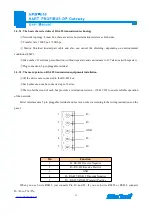
Page 14: ...he main points on RS 485 transmission equipments installation All the devices are connected to the RS 485 bus Each subsection can be connected up to 32 sites The two farthest end of each bus provides...

Page 15: ...on 1 RX Connect user device RS232 s RX 2 TX Connect user device RS232 s TX 3 GND Connect user device RS232 s GND 3 4 5 HART interface 1 2 HART LOOP HART LOOP Pin Function 1 Connect HART signal positiv...

Page 16: ...hese digrams show outside sampling resister used and the the system wiring Use internal sampling resister just to replace the 250ohm to internal resister You must select one from using internal sampli...

Page 17: ...It is recommended the HART slave instrument and gateway uses separate power supply so that the gateway can immediately establish communication with instrument 2 When configuring HART read write comma...

Page 18: ...rmation Double click on the icon to enter the main Window of software Tool Bar Toolbar interface shown as follow The function from left to right is New Save Open AddNode DelNode DelCmd Upload Download...

Page 19: ...slave node DelNode Delete a HART slave node AddCmd Add a HART command DelCmd Delete a HART command Upload Read the configuration information from the module and shown in the software Download Downloa...

Page 20: ...the response information received in HART convenient to debug 4 2 Software Usage 4 2 1 Connect to the hardware Put the DIP switch of the gateway to ON we use a serial port line to connect the gateway...

Page 21: ...bus slave If you want to use the functionality of Modbus slave click the Fieldbus in the tree view select mode as Modbus slave in the right configuration plate and then press ENTER to confirm you will...

Page 22: ...mes whether or not to clear the HART input data buffer Timeout number set the timeout clear times 4 2 3 2 Configure the fieldbus as universal mode The universal mode transparent transmission mode mean...

Page 23: ...ough the modeling software of PROFIBUS master it can t be changed Numbers of output bytes setting by the configuration software of PROFIBUS master it can t be changed Timeout clear keep of input data...

Page 24: ...numbers range is 0 5 Polling Enable Whether to use polling function Enable means to use polling function Polling circle time Set the polling circle time time interval between starting to send one ord...

Page 25: ...ode when configured in the single point mode Note When configured node numbers are more than the actual connected devices the redundant node will lead to the longer time of polling circle So it is rec...

Page 26: ...www sibotech net 25 Choose the command you want in the popup menu then click OK to exit Note the same command can only be configured once in one node...

Page 27: ...put This order is put in the polling list executed periodically Initialization output Execute the command only once when power is on Disable output the command will not generate output data Set starti...

Page 28: ...s shown below The left side is configuration commands the right side is data memory address including receive data storage address and send data storage Upper side is memory distribution of the HART s...

Page 29: ...cording to the input output bytes number by users commands You should set the correct input output bytes for each commands then click label select yes in the popup menu 4 2 7 Download configuration fi...

Page 30: ...is in the debugging mode 2 Use a serial port line to connect the gateway s RS232 port and computer RS232 serial port open the software HT 123 click Config serial setting Select the correct serial port...

Page 31: ...gateway s debug switch is in the ON state and then regain the power HPM 610 is in the debugging mode 2 Use a serial port line connected to the gateway s RS232 port and computer RS232 serial port Open...

Page 32: ...in this interface it will show the status of HART fieldbus part in the right place press Refresh button will update the data once click on Periodically refresh the software will update the data every...

Page 33: ...lly refresh will fresh command status once 7 Double click command 0 1 2 3 6 11 12 13 1 15 16 17 18 19 will show their command information command 6 17 18 and 19 can input data Press the Refresh button...

Page 34: ...bus and monitor the data that are received in HART fieldbus concrete operations are as follows 1 Firstly put the gateway s debug DIP switch to ON state and power on again Now HPM 610 is in the debuggi...

Page 35: ...om HART fieldbus will be shown in the blank place below The Checksum button only checks part of the data Here is an example In this example command 0 is composed of data head data and check code It us...

Page 36: ...memory block of 5000 bytes and these 5000 bytes are considered as input and output buffers of data exchange area Among them 0 2999 memory area acts as the storage area of the HART input data and devi...

Page 37: ...tatus 1960 2119 980 1059 The response status of the user command 2120 2391 1060 1195 Reserve 2392 1196H Universal Receive label 2393 1196L Universal Receive Error Counter 2394 2395 1197 Universal Rece...

Page 38: ...e times of gateway HART port The HART Receive counter HART communication error times The HART Receive Error counter Device 0_cmd0 Device 15_cmd0 s response status Show the response status of internal...

Page 39: ...e value will result in one trigger operation Trigger command number Trigger command number operation executed Universal mode enabled The value of 1 indicates a general transfer function is enabled oth...

Page 40: ...common ways for users to choose One is that fieldbus is defined as common mode The gateway will receive serial data in the way of 3 5 character timeout broken frame and send out the data unmodified f...

Page 41: ...will order universal reception error counter to plus 1 Before sending the general frame all users should read the universal receive label and the error counter After finishing to send the general fram...

Page 42: ...ODIBUS can read the field device data in the input buffer and can write the data to the field device in the output buffer The maximum input output bytes of PROFUBUS that HPM 610 supports is 244 bytes...

Page 43: ...ord 24 Words Input 24 Words Output Word 56 Words Input 56 Words Output Word 1 Byte Input Byte 1 Word Input Word 2 Words Input Word 4 Words Input Word 8 Words Input Word 16 Words Input Word 32 Words In...

Page 44: ...15 and receiving uses SFC 14 6 2 How STEP7 select data module Generally when the data modules include Consistent this means this data module is is length integrity Take 2 words Input Consistent as an...

Page 45: ...odules For example When user needs 20 word s input The data number reading form Modbus slave through PLC is 20 words user can directly select modules no less than 20 word s input 32words Input 64words...

Page 46: ...www sibotech net 45 7 2 Installation Method Using 35mm DIN RAIL INSTALLATION...

Reviews: