ITALIANO
ENGLISH
FALCO AF 2500
16
COD. 104060 Rev.1
INSTALLAZIONE
POSIZIONAMENTO MACCHINA
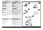
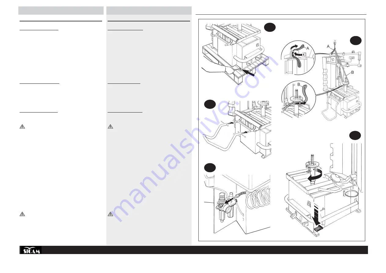
» Svitare i 2 dadi che fissano la macchina al pallet (fig.9).
»
Passare la fascia A di sollevamento (mod. DR250 di mt. 1) e la fascia
B (mod.FA650 di mt.3) come da fig.10 facendo attenzione nel non
schiacciare i tubi di alimentazione dei cilindri.
»
Sollevare la macchina e posizionarla nella zona prestabilita rispettando
le distanze indicate in fig.8 (pag.14).
»
Montare il tubo portagomma come da fig.11.
COLLEGAMENTO PNEUMATICO
»
Collegare la macchina alla rete pneumatica come da fig.12.
COLLEGAMENTO ELETTRICO
» Collegare la macchina alla rete elettrica.
OGNI INTERVENTO SULL’IMPIANTO ELETTRICO, ANCHE DI
LIEVE ENTITÀ, DEVE ESSERE EFFETTUATO DA PERSONALE
PROFESSIONALMENTE QUALIFICATO !
»
Controllare la conformità tra la tensione di linea e quella indicata sulla
targa della macchina.
»
Collegare il cavo dell’alimentazione a una spina conforme alle norme
Europee o alle norme del paese di destinazione della macchina. La
spina deve essere provvista obbligatoriamente del contatto di terra.
»
Verificare l’efficacia della messa a terra.
»
La macchina deve essere allacciata alla rete tramite un sezionatore
onnipolare conforme alle norme Europee, con apertura dei contatti di
almeno 3mm.
N.B.
: I DISEGNI DEGLI SCHEMI ELETTRICI SONO SITUATI NEL
QUADRO ELETTRICO DELLA MACCHINA
IL COSTRUTTORE DECLINA OGNI RESPONSABILITÀ PER LA
MANCATA OSSERVANZA DI DETTE PRESCRIZIONI.
È molto importante, per il funzionamento regolare della
macchina, che alla pressione verso il basso del pedale
invertitore corrisponda un moto rotatorio in senso orario
dell’autocentrante (fig.13).
9
10
11
12
13
INSTALLATION
POSITIONING THE MACHINE
» Release the 4 nuts fixing the machine to the pallet (fig.9).
» Wrap the lifting sling A (mod. DR250 of 1 m) and sling B (mod.FA650
of 3 m) as in fig.10 taking care not to crush the cylinder supply pipes.
» Lift the machine and place it in the established area respecting the
distances indicated by the fig.8 (pag.14).
»
Mount the tyre-holder pipe as in fig.11.
PNEUMATIC CONNECTION
»
Connect the machine to the pneumatic system as in fig.12.
ELECTRICAL CONNECTION
»
Connect the machine to the mains.
ALL WORK ON THE ELECTRICAL SYSTEM, INCLUDING MINOR
OPERATIONS, MUST BE CARRIED OUT BY PROFESSIONALLY
QUALIFIED PERSONNEL !
»
Check that the mains supply voltage is the same as that shown on the
registration plate.
»
Connect the supply cable to a plug that conforms with European norms
or to the norms of the country in which the machine is used. The plug
must have an earth terminal.
»
Check that the earth connection is effective.
»
The machine must be connected to the mains through a multipole
isolating switch which conforms with European norms and with con-
tact openings of at least 3 mm.
N.B.
: THE ELECTRICAL CIRCUIT DIAGRAMS ARE LOCATED IN THE
ELECTRICAL PANEL OF THE MACHINE
THE MANUFACTURER DECLINES ALL RESPONSIBILITY FOR FAIL-
URE TO OBSERVE THE ABOVE INSTRUCTIONS.
It is very important for the correct operation of the machine
that downward pressure on the inverter pedal produces a
clockwise rotation of the chuck
(fig.13).
Summary of Contents for FALCO AF 2500
Page 45: ...N 104036 Rev 0 OPTIONAL...
Page 46: ...N 104362 01 Rev 0 FALCOAF 2500...
Page 47: ...N 104362 02 Rev 0 FALCOAF 2500...
Page 48: ...N 104362 03 Rev 0 FALCOAF 2500...
Page 49: ...N 104362 04 Rev 0 FALCOAF 2500...
Page 50: ...N 104362 05 Rev 0 FALCOAF 2500...
Page 51: ...N 104361 01 Rev 0 FALCOAF 2500...
Page 52: ...N 104361 02 Rev 0 FALCOAF 2500...
Page 53: ...N 104361 03 Rev 0 FALCOAF 2500...
Page 54: ...N 104361 04 Rev 0 FALCOAF 2500...
Page 55: ...N 104361 05 Rev 0 FALCOAF 2500...
Page 56: ...N 104338 01 Rev 0 FALCOAF 2500...
Page 57: ...N 104338 02 Rev 0 FALCOAF 2500...
Page 58: ...N 104338 03 Rev 0 FALCOAF 2500...
Page 59: ...N 104338 04 Rev 0 FALCOAF 2500...
Page 60: ...N 104338 05 Rev 0 FALCOAF 2500...
Page 61: ......


